
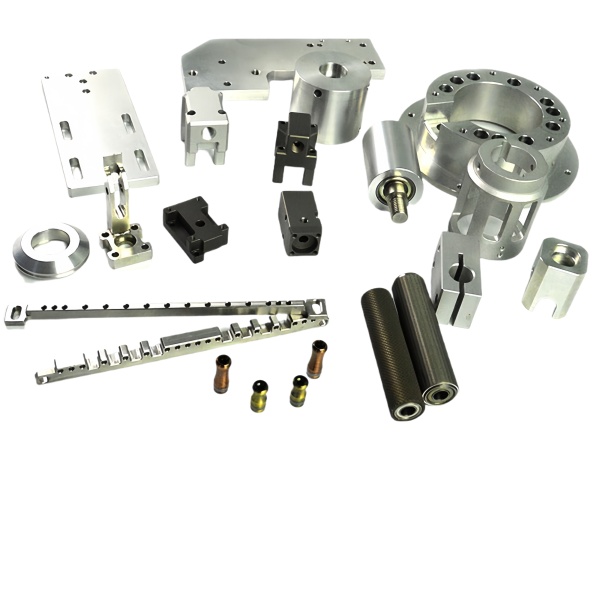
Fixture rigidity determines whether the workpiece is held securely or deflects under cutting force
A machined fixture—whether it is a welding jig, an inspection gauge, a machining vise jaw, or an assembly holding device—must be significantly more rigid than the workpiece it holds. The rule of thumb in fixture design is that the fixture’s static deflection under maximum expected load should be less than 1/10 of the workpiece’s positional tolerance. If the workpiece must be held within 0.05 mm of nominal, the fixture should deflect less than 0.005 mm under the worst-case clamping and cutting force.
We design aluminum fixtures with wall thicknesses and rib patterns calculated to meet this deflection criterion using FEA (finite element analysis) for complex geometries or hand calculations (beam theory) for simple plate-and-rib designs. For a typical aluminum fixture plate (300 × 200 × 20 mm) clamping a 50 kg workpiece with 500 N of cutting force, the deflection at the center of an unsupported plate would be roughly 0.03 mm—too much for precision work. Adding two longitudinal ribs (20 mm deep × 10 mm wide) reduces the deflection to about 0.004 mm, meeting the 1/10 rule.
Connector rod concentricity between its two end features determines the alignment accuracy it can transmit
A connector rod—also called a tie rod, link, or strut—transmits force and alignment between two points. If the rod has threaded ends, bored ends, or bearing seats at both ends, the concentricity of these two features relative to each other (and relative to the rod’s axis) determines how accurately the alignment is preserved when the rod is installed.
We hold end-to-end concentricity to 0.02 mm TIR for general-purpose connector rods and to 0.005 mm TIR for precision linkage rods (used in optical mounts, measurement equipment, or mechanisms where angular error amplifies over distance). Achieving tight concentricity requires turning both end features in the same setup as the OD (for turned rods) or finish-machining both ends between centers after initial profiling (for milled rods). The cost difference between 0.02 mm and 0.005 mm TIR is approximately 30–40 % due to the extra setup time and more frequent inspection.
Mount base flatness affects whether the fixture sits true or rocks on the machine table
The bottom surface of a fixture mount—the surface that contacts the machine table, the CMM granite, or the assembly bench—is the datum from which all other features are referenced. If this surface is not flat, the entire fixture tilts when bolted down, introducing angular error into every feature that was machined assuming the fixture was level.
We machine fixture mounting surfaces to 0.01 mm flatness over the full contact area using a facing operation with a large-diameter face mill (matching or exceeding the mount’s width) taking a light finishing pass at 0.05 mm depth of cut. After machining, we verify flatness by placing the fixture on a grade-A granite surface plate and measuring gap with a feeler gauge at four corners and the center. Any gap exceeding 0.01 mm triggers re-facing or hand-scraping (for cast-iron fixtures) until flatness is achieved.
Aluminum vs. steel for fixtures: choose based on usage frequency and required life
The material choice for a machined fixture involves a tradeoff between weight (aluminum wins), wear resistance (steel wins), and thermal stability (both are adequate but steel has lower CTE):
- Choose aluminum (6061-T6): Fixtures that are moved frequently (robot end-of-arm tooling, portable inspection gauges), fixtures where weight matters (aerospace assembly tools, handheld devices), and fixtures with short-to-medium production runs (< 10,000 cycles). Aluminum fixtures can be hard-anodized (Type III) on wear surfaces to extend life by 3–5× compared to bare aluminum. Cost: moderate raw material cost offset by faster machining speed (~25 % faster than steel).
- Choose steel (1018/1045 or pre-hardened 4140): High-production fixtures (> 50,000 cycles), fixtures subject to heavy impact or abrasion (forging dies, stamping die sets), and fixtures where thermal stability is critical (CMM fixtures, long-duration inspection gauges). Steel fixtures can be through-hardened (HRC 45–55) for maximum wear resistance. Cost: higher raw material cost per kg but longer service life may result in lower total cost of ownership for high-volume production.
- Cast iron (GG20/GG25): Large fixtures (> 500 mm in any dimension) where damping capacity matters (vibration absorption during machining) and where casting geometry allows features that would be expensive to machine from solid stock. Cast iron has excellent damping (10–20× aluminum) due to its graphite flake microstructure. Used primarily for machine bases, large inspection plates, and welding jigs.
How we validate a custom fixture before shipping it to the customer’s production floor
For custom-designed fixtures (not off-the-shelf standard items), our validation protocol includes:
- First-article dimensional verification: Full CMM inspection of all critical datums, locating features, and clamp interfaces. Results compared to the CAD model with GD&T callouts. Any deviation > 10 % of tolerance band triggers engineering review before production use.
- Fit check with customer-supplied workpiece: If the customer sends us a sample workpiece (or a 3D-printed surrogate), we verify that the fixture clamps correctly, locates accurately, and releases without binding. Photos document the fit-up.
- Repeatability test: Load and unload the workpiece (or surrogate) 10 times, measuring the position of a reference feature after each cycle. Acceptance: range (max – min) < 1/3 of the positional tolerance. This confirms that the fixture produces consistent results across multiple cycles.
- Rigidity test (optional): Apply a simulated cutting force (dead weight or hydraulic load) to the workpiece while clamped in the fixture. Measure deflection with a dial indicator. Confirm deflection < spec (typically < 0.01 mm at max rated load).
- Documentation package: Fixture drawing (revision-controlled), CMM report, repeatability test data, and setup instructions (torque values, sequence, any special handling notes). This documentation travels with the fixture and stays with it throughout its service life.
This part sits inside our CNC Machining Parts range. Across the cnc machining parts pages you will find the process notes, common materials and inspection points behind every product in the family.
Specifications
| Item | Aluminum CNC Machined Fixtures Mounts and Connector Rods |
|---|---|
| Brand | AUNOV |
| Designing | Send the drawing, or a connector sample we can measure, the quotation comes back with a manufacturability review attached. |
| Tooling | Tooling designed and cut in house, each die held against your part number. |
| Samples | Pre-production samples of the connector ship with a full dimensional report and material certification. |
| Materials | Stock for this part leads with aluminium, alongside carbon steel (SPCC / DC01), 304 / 316 stainless steel, brass and copper, and the grade is fixed at the drawing review. |
| Surface finish | Surface treatment per the drawing: plating, e-coat, powder coating, anodising, passivation, selected against the drawing requirement. |
| Processing | Staged deep drawing with in-line annealing where needed, with piercing and finish machining under the same roof. |
| Equipment | From 5 to 500 T of press capacity across mechanical and hydraulic lines; CNC turning and milling cells plus a climate-controlled CMM room. |
| Tolerance | +/-0.1 mm as-drawn, +/-0.03 mm after machining. |
| Delivery terms | Prices FOB, with DDP for EU and US on request, T/T or L/C, with D/P for repeat business, call-off scheduling supported. |
Related Products


Request a Quote for This Part
Send a drawing or sketch — get material advice, tooling cost and a per-piece price within 24 hours (working days).