
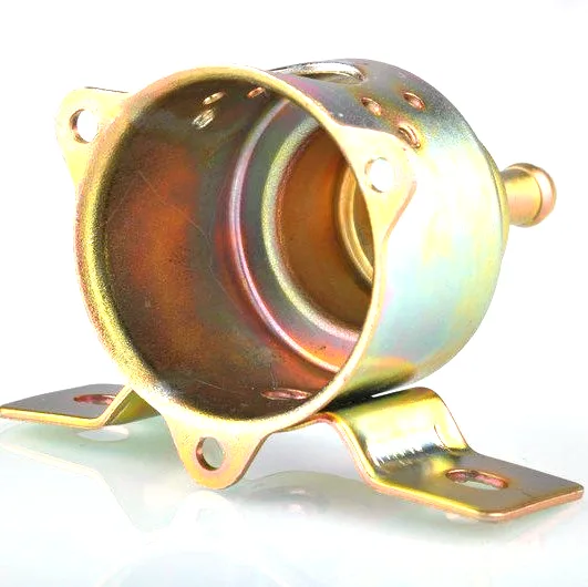
A stepper is only as good as its air gap
A hybrid stepping motor produces motion by holding a rotor in a magnetic field that advances in discrete steps, and the size of those steps depends on the gap between the rotor teeth and the stator teeth. That gap is a fraction of a millimetre. It is not set by any single part – it is set by where the stator sits inside the housing and where the rotor sits relative to the stator – which means the housing is, in effect, the fixture that establishes the motor’s accuracy. A housing whose bore is round and whose bearing seats are coaxial gives an even gap and clean steps; a housing that is oval or whose bearing seats are offset gives a gap that varies around the circumference, and the motor loses torque, runs louder and steps less precisely. This page is about designing and drawing a stepping motor housing as a precision part.
Roundness: the gap the customer never measures
The stator lamination stack is pressed into the housing bore or clamped against it, so the bore shape transfers directly to the stator. If the bore is oval by even a few hundredths of a millimetre, the gap is tight on two sides and loose on the other two. The consequences:
- Torque falls, because the tight sides do most of the magnetic work and the loose sides contribute little.
- Detent torque becomes uneven, which shows up as a motor that cocks or vibrates at certain positions.
- Noise rises, because the uneven gap modulates the magnetic force as the rotor turns.
We control bore roundness by drawing the bore to a controlled diameter and sizing it on the final stage where the print demands it, then measuring roundness with a bore gauge or on the CMM. For a stepper housing the bore is a metrology feature, not a clearance feature, and we treat its tolerance accordingly.
Coaxial bearing seats: the two ends must agree
A stepper has a bearing at each end of the rotor shaft, and those two bearings must be coaxial to within a small fraction of the air gap – otherwise the shaft tilts, the gap closes on one side, and the motor either rubs or loses torque. The two bearing seats are at opposite ends of a fairly long housing, so their coaxiality is a stack of the housing’s own tolerance and the seat-to-seat alignment:
| Bore | Locates the stator; sets the roundness that makes the gap even. |
|---|---|
| Front bearing seat | Locates one end of the shaft; must be concentric to the bore. |
| Rear bearing seat | Locates the other end; must be coaxial to the front seat, across the full length. |
| Mounting face | Perpendicular to the axis, so the motor bolts down without tilting the shaft. |
We hold these four features as one controlled group, and we can size the bearing seats in a finishing operation so their diameter and coaxiality are set together rather than inherited from the draw. On a long housing this coaxiality is the hardest tolerance on the drawing, and it is the one that decides whether the motor runs smooth or rubs.
The step angle and why geometry matters to it
The rotor advances by one tooth pitch per electrical cycle, and the step angle is a property of the tooth counts and the phases. But the housing enters the story through the gap and through the centring of the rotor. An even gap keeps the holding torque constant from step to step, which is what a controller needs to position reliably. An uneven gap or a tilted shaft makes the holding torque vary around the revolution, and a controller that assumes a constant torque will mis-position by a fraction of a step at the weak points – which is exactly the error a machine tool or a 3D printer cannot tolerate. So a tight housing is not a luxury on a stepper; it is what makes micro-stepping work.
Heat, expansion and the gap that closes
Steppers run hot – they hold current to hold position, so the winding stays energised even at standstill, and a small frame can reach a case temperature well above 60 °C. As the housing warms it grows, and the rotor and stator grow at their own rates, so the air gap changes with temperature. A housing made from a material with a stable, predictable expansion lets the designer budget that change; a housing whose dimension moves unpredictably does not. This is one reason the housing material for a stepper is agreed with the motor designer rather than chosen for cost alone, and why we confirm the grade with the drawing review.
Stator and rotor retention
Two fits keep the motor’s internals where they belong, and both are housing features:
- Stator retention. The stack is either pressed into the bore or bonded; a press fit has to be tight enough to hold the stack against torque reaction but not so tight that it deforms the bore or crushes the laminations. We set the bore so the customer’s intended fit is achieved, and check the result on the first article.
- Rotor and bearing retention. The bearing seats are sized for the specified interference, so the bearings neither spin in their seats nor preload the shaft. Because these seats are often finished after drawing, their diameter is one of the tightest bands we quote.
Frames, sizes and mounting
Stepper housings come in recognisable frame sizes, from the small square frames used in instruments and 3D printers to the larger NEMA 23 and 34 frames used in automation. Two mounting styles dominate: a square flange with four bolt holes on a standard pitch, and a round body with a face mount. In both, the mounting face must be square to the axis so the motor sits straight, and the bolt pattern must be on centre so the shaft aligns with the driven part. We form the flange and pierce the bolt pattern in-die, and we control the face-to-axis perpendicularity so the motor does not cock when it is bolted to a plate.
A stepping motor housing is sized by its frame, 28 to 86 mm
- Body: 28-86 mm square or round, matching common frames.
- Length: 25-120 mm.
- Wall: 0.8-2.0 mm.
- Features: sized stator bore, front and rear bearing seats, square or round mounting flange with bolt pattern, cable or connector exit, perpendicular mounting face.
Holding two bearing seats coaxial over a long housing
Can you hold the two bearing seats coaxial over a long housing?
Yes – we hold bore, front seat, rear seat and mounting face as one controlled group, and can finish the seats after drawing so their coaxiality is set in one operation.
How round is the bore?
Roundness is measured with a bore gauge and the CMM; the band is set from your air gap budget, because the bore shape transfers straight to the stator.
Does the housing material affect the air gap?
Yes – as the motor heats, the housing grows and the gap changes, so we agree the grade with your motor designer rather than choosing on cost alone.
Can you pierce the standard bolt pattern in-die?
Yes, and we control the mounting face perpendicularity to the axis so the motor bolts down square.
Frame size, stator bore roundness and coaxiality set the drawing’s inputs
Tell us the frame size and mounting style, the stator bore and the roundness budget, the bearing seat diameters and the coaxiality you need across the length, the stator retention method, the mounting face tolerance and the cable exit. Those inputs set the stage plan, the sizing operations and the tolerance group – which is what keeps the air gap even, the holding torque flat, and the steps exactly where the controller expects them.
Automotive Motor Components is the parent range for parts like this one; the overview page gathers the tooling logic, finishing options and tolerance notes that apply across the family.
Specifications
| Item | Sheet metal deep drawing stepping motor housing |
|---|---|
| Brand | AUNOV |
| Designing | Driven by your drawing or a physical sample – samples are reverse-measured into a controlled drawing; the approved drawing is kept as the controlled master. |
| Tooling | Progressive and drawing dies are designed and built in house, so die cost stays transparent, and the charge is refundable against agreed volumes. |
| Samples | Prototype and pre-production samples are provided against the drawing, so the part is proven before it is made in volume, and later batches are gauged back to the signed sample. |
| Materials | Carbon steel, 304 / 316 stainless steel, aluminium and brass are held in stock; the drawing review fixes the final grade. |
| Surface finish | Corrosion protection comes from zinc or nickel plating, housings additionally take powder coating or electrophoresis, and laser etching can be added on request. |
| Processing | From coil or blank, deep drawing with in-process annealing thins walls evenly; the sequence then runs trim, pierce, form and finish. |
| Equipment | 5-250 T mechanical presses and 250-500 T hydraulic presses, in-line annealing furnace, CNC turning for secondary work. |
| Tolerance | +/-0.1 mm on formed features and +/-0.2 mm on overall lengths; tighter bands confirmed against the die before quoting. |
| Delivery terms | FOB, with DDP offered for EU and US addresses, payment by T/T or L/C, quoted in USD or EUR; call-off schedules are supported. |
Related Products

Request a Quote for This Part
Send a drawing or sketch — get material advice, tooling cost and a per-piece price within 24 hours (working days).