
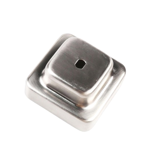
The bolt circle is a contract, not a dimension
A motor bell looks like a drawn cover with holes in the flange. It is not. It is the mechanical interface between two assemblies that were designed separately, and the bolt circle is the clause of that contract that everything else depends on. If the pitch circle diameter is wrong by 0.3 mm, the bell will not bolt to the gearbox, the stator or the mounting plate, and no amount of care taken with the drawn geometry will recover the situation. This is why the bolt pattern deserves to be treated as its own toleranced feature rather than as a set of holes placed on a convenient circle.
The drawing convention that gets this right is a position tolerance applied to the hole pattern relative to a datum established by the bell’s own locating feature, usually the bearing bore or the pilot diameter. The wrong convention, and the common one, is a set of hole locations dimensioned from the outer edge, which ties hole position to the trim edge of a drawn part. The trim edge is the least reliable surface on a drawn bell, so dimensioning from it converts trim variation into hole position variation with no benefit to anyone.
Pitch circle, hole size and the clearance stack
The bolt pattern has three numbers and they interact: pitch circle diameter, hole diameter and hole position tolerance. Between them they define the clearance available for the fastener, and that clearance has to absorb every variation in the whole stack, including the mating part. A pattern drawn with a tight position tolerance and a hole that is a close fit will assemble on the bench and fail on the line, because the mating part brings its own variation and the two are additive.
A useful discipline is to work out the worst case before choosing the tolerance. Take the position tolerance on the bell, add the position tolerance on the mating part, add the fastener’s own diameter variation, and compare the total with the difference between the hole diameter and the fastener diameter. If the clearance is smaller than the sum, the joint will interfere at some point in the batch even though both parts passed inspection. Sizing the holes 0.3 to 0.5 mm over the fastener is the ordinary answer for a rigid, well located joint, and it costs nothing in strength because the bolt carries the shear through friction and clamping rather than through bearing on the hole wall.
- Position the pattern from the bearing bore or the pilot diameter, never from the trim edge.
- Convert any angular hole spacing to a linear figure at the pitch radius before writing a tolerance on it.
- Check the clearance stack including the mating part, not only the bell.
- Do not use a hole pattern to locate the bell. Locate it on the pilot diameter and let the bolts clamp.
Bell depth and the gap it controls
The depth of the bell is not a packaging dimension. In most motors it sets the axial position of the rotor relative to the stator, and therefore the air gap at the ends of the stack. A depth variation of 0.2 mm moves the rotor by 0.2 mm, which on a small motor with a 0.5 mm nominal air gap is a substantial fraction of the whole magnetic working clearance. The effect is not symmetric: a rotor that sits too far one way increases the fringing field and the axial force, while the opposite direction can cause the rotor to drag.
Depth on a drawn bell is controlled by the press, not by the drawing. The punch stroke sets the depth, and the stroke is affected by material thickness variation, springback and thermal drift over a shift. A drawn bell therefore needs the depth checked as a process parameter during the run, not only as a first article dimension. Where the depth is critical, the honest engineering answers are to add a restrike station that sets the depth positively against a hard stop, or to make the critical axial face a machined feature so that it is set by a tool rather than by a stroke. Both cost money and both are more reliable than a note on the drawing asking for a tight tolerance that the process cannot hold.
Runout and concentricity are two different inspections
Runout and concentricity are routinely used as if they were the same thing, and on a motor bell they are not. Concentricity compares the axis of one feature with the axis of another and is a property of the two axes alone. Runout compares a surface, as it rotates about a datum axis, with that axis, and therefore includes the roundness of the surface, its straightness and its orientation. A bell with a perfectly concentric but slightly lobed bearing bore will pass a concentricity check and fail a runout check, and it is the runout figure that predicts whether the shaft will whirl.
For a bell carrying a bearing, the measurement that matters most is the total runout of the bore relative to the mounting face, because that is the pair of features that positions the shaft. A figure of 0.03 to 0.05 mm total runout is a normal working requirement on a small motor bell and is achievable when the bore is machined after forming in a single setup with the mounting face as the locating feature. Achieving it without machining is much harder, because the drawn geometry carries the tool’s own eccentricity and the material’s thickness variation into the finished bore.
The bearing seat: a press fit needs a roundness number
A bearing seat holds the outer race by interference, which means the seat has to be round as well as correctly sized. This is the point that is most often missed, because an interference fit is specified by a diameter and a tolerance and that is what goes on the drawing. The problem is that a bearing outer race is a stiff ring, and pressing it into a lobed bore does not remove the lobing; it transfers it into the race. The race then becomes slightly non-circular, the rolling elements see a varying load, and the motor develops a once-per-revolution noise that is very difficult to diagnose later.
Roundness of the bearing seat bore should be called out separately, and a figure of 0.01 to 0.02 mm is what a small motor bearing needs. That figure cannot be achieved by drawing alone. The bore is normally machined after forming, in a single setup with the mounting face located, so that roundness, size and perpendicularity are produced by the same tool motion. It is also worth stating the process explicitly, because a bell that has a machined bore must not have that bore deformed afterwards by a subsequent operation such as a paint cure or a heavy press operation.
How we verify a motor bell before it ships
A motor bell is verified against the features that decide whether the motor runs true and stays put: the bolt circle, the bearing seat and the bell-to-shaft runout. The first article carries the full CMM report; production bolt holes and bores are gauged on a sampling plan with the critical ones on every piece.
- CMM the bolt-circle position and hole size; the circle must sit concentric to the bore within the stated runout, or the motor binds on its feet.
- Measure the bearing seat diameter and roundness for the press fit; a seat that is round but oversize lets the bearing spin, one that is undersize cracks the bell.
- Check bell depth and the air-gap face so the rotor cannot rub the stator at temperature.
- Runout of the open face relative to the bore axis, held within the print limit, because the bell is the rotor reference.
- Verify the flange flatness so the bell pulls down square to the frame without distorting the bore.
- File the CMM report, material certificate and bolt-circle record under the part number for repeat orders.
For derivative motors we keep the bolt circle and bearing seat as the master features and let the bell depth and wall vary around them, because those two are what the production line and the test rig are already set up to, and a new bell that reuses them is a setting change rather than a tool change. We flag that split on the quotation so a family of motors can share one proven bell geometry instead of paying for several.
The design decisions behind a part like this — draw ratio, wall thinning, radii and trim — are worked through with numbers in our deep drawn covers guide, and the Precision Deep Drawn Parts pages collect the rest of the family.
Specifications
| Item | Steel Deep Drawn Motor Bell with Bolt Pattern |
|---|---|
| Brand | AUNOV |
| Designing | Share your print, or send a part to be measured, a manufacturability review comes back with the quotation. |
| Tooling | Tooling designed and cut in house, stored under your part number. |
| Samples | Pre-production samples ship with a dimensional report and material certificate. |
| Materials | Carbon steel (SPCC / DC01) leads the stock list for this part, alongside 304 / 316 stainless steel, aluminium, brass and copper, per the drawing. |
| Surface finish | Zinc, nickel or chrome plating, e-coat, powder coat, anodising or passivation, each selected against the drawing requirement. |
| Processing | Staged deep drawing with in-line annealing where needed, pierced and finish-machined on the same floor. |
| Equipment | Mechanical presses 5-250 T and hydraulic presses 250-500 T, CNC cells plus a temperature-controlled CMM room. |
| Tolerance | Drawn tolerances held to +/-0.1 mm, +/-0.03 mm on machined surfaces. |
| Delivery terms | FOB standard, DDP offered for EU and US, payment T/T or L/C, D/P for repeat accounts, call-off scheduling supported. |
Frequently Asked Questions
Why is the bolt circle called a contract rather than a dimension?
A motor bell is the mechanical interface between two assemblies that were designed separately, and the bolt circle is the clause everything else depends on. Get the pitch circle diameter wrong and the bell will not bolt to the gearbox, the stator or the mounting plate, and no amount of care with the drawn geometry recovers the situation.
Why should the hole pattern not be dimensioned from the trimmed outer edge?
The trim edge is the least reliable surface on a drawn bell, so dimensioning holes from it converts trim variation into hole position variation with no benefit to anyone. The correct convention is a position tolerance applied to the hole pattern against a datum established by the bell’s own locating feature, usually the bearing bore or the pilot diameter.
Runout or concentricity: which one applies here?
They are two different inspections and the drawing should say which is meant. Concentricity relates the bolt circle and the bearing seat to the axis the rotor actually turns about, while runout describes how the bell behaves as it rotates, and a part can pass one and fail the other.
What does the bearing seat need that the rest of the bell does not?
A press fit cannot be specified by diameter alone, because a bore that measures correct at two points and is out of round will not hold the bearing evenly. The seat therefore needs a roundness number alongside its size, which is why it gets more attention than the flange it was drawn with.
Related Products



Request a Quote for This Part
Send a drawing or sketch — get material advice, tooling cost and a per-piece price within 24 hours (working days).