
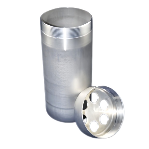
A threaded ring cap on a deep-drawn aluminium cylinder only earns its cost when the thread, the cap seat and the drawn wall are made to work as one joint. On this geometry the engineering does not live in the body – it lives in the closure. This page covers the wall budget the thread demands, the roundness a cap seals against, the leak paths we design out, and the acceptance checks every lot carries off our floor.
Why the cap thread sets the cylinder wall budget
On a turned part you cut a thread into whatever wall is there. On a drawn cylinder the wall is the material budget for the whole component, so the thread has to be calculated first, not dropped in last. A rolled or cut M-series thread needs an engagement depth of roughly 0.6 to 0.8 times the pitch per flank; on a 1.5 mm pitch that means the wall under the thread must carry about 1.2 mm of formed metal before you count any sealing land beneath it. We routinely see drawings that call a 1.0 mm nominal wall and a full-depth thread in the same region – that combination strips at a quarter of the torque a customer assembly line will apply.
The split we use in practice: body walls at 0.8 to 1.2 mm where the cylinder only contains, and a locally thickened neck at 1.8 to 2.5 mm where the ring cap threads on. If the whole body must stay light, the neck is produced from a pre-formed cup with a heavier hold region at the open end, or the thread land is machined from a solid thickening drawn into the mouth. What almost never works is threading a thin as-drawn wall directly and hoping the cap torque stays gentle – assembly lines are never gentle, and a stripped neck is a field return, not a shop adjustment.
- Engagement length is sized from the proof torque, not from the thread diameter alone.
- The neck wall is treated as a load-bearing section, not as leftover material.
- Where weight is fixed, we move the strength into a short thickened land rather than thinning everywhere.
Holding the body round after the ring cap is torqued
A capped cylinder is a torque-loaded structure. When the ring cap is wrenched to 15 or 25 N-m, the reaction loads the neck and the body below it, and an out-of-round body converts that torque into local wall stress that the seal then has to absorb. Roundness therefore gets specified twice on our drawings: as-drawn ovality within 0.3 mm on diameters up to 100 mm, and post-assembly ovality after a torque-undo-torque cycle, within 0.5 mm. The second number is the one that matters for sealing, and it only holds if the draw schedule leaves balanced residual stress in the wall rather than a spiral pattern that relaxes under load.
Aluminium work-hardens through each draw stage. A three-stage schedule on a 60 mm diameter part usually starts from 1.5 mm blanks, takes a first reduction near 40 percent, then runs intermediate anneals at 340 to 380 degrees C for 20 to 30 minutes. Skip the anneal and the neck flares outward on the second hit; over-anneal and the wall wrinkles on the third because the flange has lost the strength to resist buckling. We tune the schedule against the torque test, not only against the dimensional report, because a part that measures round cold and goes oval under clamp load is a part that leaks in service.
- Draw ovality is measured on the green shell, before any machining, to confirm the schedule is balanced.
- The torque-undo-torque cycle is run on the first article to expose residual-stress relaxation.
- Neck perpendicularity to the body axis is held under 0.5 degrees or the gasket rides up on one side.
Rolled, cut, or machine-the-land: choosing the thread route
There are three ways the cap thread on these cylinders comes to exist, and they differ in what they cost the part. Thread rolling after the draw displaces metal rather than removing it, raising the neck surface to roughly 15 percent stronger in shear – the right choice whenever the cap will be removed and retightened repeatedly, such as refillable housings. Rolling demands a ductile, fully annealed neck and a roundness better than 0.15 mm, or the rolls skid and burnish instead of forming. Thread cutting on a lathe holds class 6H or 6G fits without fuss and tolerates a wider incoming diameter, but it severs grain flow and leaves a notch that cracks first under vibration – acceptable for install-once caps, poor for service-loop products. The third route, machining the thread into a thickened land that was drawn in, gives the best thread quality and the least efficient material usage, so we reserve it for pressure-rated cylinders at 50 mm diameter and below, where that same land also carries an O-ring gland.
- Rolling: strongest, cheapest per piece, but unforgiving of a hard or out-of-round neck.
- Cutting: most tolerant of incoming variation, weakest under vibration and repeated torque.
- Machine-the-land: best quality and best for a combined thread-plus-gland, worst on material.
The three leak paths a capped drawn cylinder actually develops
Three failure routes account for nearly every field leak on capped drawn cylinders, and none of them shows up on a simple go/no-go thread gauge. The first is the thread helix itself – a 6G fit is a clearance fit, so gas-tight designs need a separate seal, either an O-ring in a machined gland on the neck or a gasket land where the cap bottom face seats. The second is cap wobble from an out-of-perpendicular thread axis; if the neck tilts more than 0.5 degrees relative to the body axis, the gasket sees a gap on one side no matter how much torque is applied. The third and sneakiest is draw texture on the sealing land – as-drawn surface finish runs Ra 0.8 to 1.6 um, and any land that seals directly must be machined or burnished below Ra 0.4 um or it leaks along the lay of the tool marks.
Our drawings therefore separate the sealing diameter from the thread diameter explicitly and give the land its own roughness callout instead of inheriting the as-drawn finish. On pressure applications we proof-test at 1.5 times working pressure with the cap torqued to specification, holding for five minutes against a bubble or flow-rate acceptance limit, because a thread that seals at hand torque and weeps at spec torque is a real and common defect that a dimensional report will never catch.
Anneal window for 3003 versus 5052 necks
Alloy choice on this product is not aesthetic. 3003 draws beautifully – a wide process window, forgiving of a missed intermediate anneal, stable across 340 to 380 degree C cycles – but it yields early, so a 3003 neck under a 25 N-m cap will creep its threads over time in warm service. 5052 holds roughly 40 percent more torque per thread length, which is why pressure or vibration service gets 5052, but its draw window is narrower and it needs a genuine solution to springback: expect 2 to 3 degrees of diameter recovery on drawn necks, which we measure and pre-compensate in the die rather than chasing on the press. Mixed assemblies – a 5052 cap threading onto a 3003 body – work only when the thread engagement exceeds 1.2 diameters, otherwise the softer body thread is the weak link and we say so on the manufacturability review rather than let the customer discover it.
- 3003 is the default for static, low-torque, cost-driven bodies.
- 5052 is specified wherever the cap sees proof pressure or vibration.
- Springback is measured per die and fed back into the punch-and-die sizing.
How we verify capped cylinders before they ship
Verification is written per part number and aimed at the characteristics that actually fail: thread function, wall at the neck, roundness of the sealing land, and the assembled leak rate. The first article carries the full report; production lots are gauged on a defined sampling plan and pressure-tested on a fraction or on every piece where the customer’s specification demands it.
- Measure the neck thread – pitch, flank angle and functional size with go and no-go gauges, plus a 100 percent engagement check of the actual production cap on the first ten pieces of every lot.
- Verify wall thickness at the thread land and at mid-body with an ultrasonic gauge, eight points per part, minimum wall versus nominal recorded against the drawing.
- Check roundness and perpendicularity of the sealing land on the CMM, with the cap-axis tilt limit of 0.5 degrees enforced on pressure designs.
- Torque-cycle one part per lot to specification, remove the cap, and re-measure the neck diameter and thread gauge fit to confirm no permanent set.
- Proof-test pressure-rated lots at 1.5 times working pressure for five minutes; any weep rejects the lot back to 100 percent leak testing.
- File the dimensional report, material certificate and torque-cycle data against your part number so repeat orders inherit the exact verified schedule.
Choosing between drawing, machining and welding comes down to the shape of the part: the guide to deep drawn covers sets out where each route wins, and the overview page links through to the full Precision Deep Drawn Parts range.
Specifications
| Item | Aluminum Deep Drawn Cylinders with Threaded Ring Cap |
|---|---|
| Brand | AUNOV |
| Designing | Send the drawing, or a sample we can measure, a manufacturability review comes back with the quotation. |
| Tooling | Every die designed and built in our toolroom, held and maintained under your part number. |
| Samples | Pre-production samples ship with dimensional data and material certification. |
| Materials | Aluminium leads the stock list for this part, alongside carbon steel (SPCC / DC01), 304 / 316 stainless steel, brass and copper, and the grade is fixed at the drawing review. |
| Surface finish | Finish options: plating, e-coat, powder coating, anodising or passivation, per the drawing. |
| Processing | Progressive deep draw stages with in-line annealing as the draw ratio demands, then pierced and machined in house. |
| Equipment | Press capacity from 5 to 500 T across mechanical and hydraulic lines, CNC turning centres, climate-controlled CMM room. |
| Tolerance | As-drawn tolerance +/-0.1 mm, with machined features to +/-0.03 mm. |
| Delivery terms | Standard terms FOB, DDP offered to EU and US, payment T/T or L/C, D/P for repeat accounts, blanket orders and call-offs supported. |
Frequently Asked Questions
Why can we not have a thin wall and a full-depth cap thread?
Because the thread needs metal to bite into. A rolled or cut thread wants engagement of roughly 0.6 to 0.8 times the pitch per flank, so on a 1.5 mm pitch the wall under the thread has to carry about 1.2 mm of formed metal before you count any sealing land below it. A drawing calling a 1.0 mm nominal wall with a full-depth thread in the same region strips at a quarter of the torque an assembly line applies.
How do you solve it without making the whole cylinder heavy?
By splitting the budget: body walls at 0.8 to 1.2 mm where the cylinder only has to contain, and a locally thickened neck at 1.8 to 2.5 mm where the ring cap threads on. The thickening can come from a pre-formed cup with a heavier hold region at the open end, or the thread land can be machined from material drawn into the mouth.
Should the thread be rolled, cut or machined from a land?
Rolled thread work-hardens the surface and suits ductile alloy and long runs, cut thread suits shorter runs and harder tempers, and machining the land out of a thickened mouth suits thin walls that still have to carry real torque. The choice is made from the alloy temper and the torque rather than from habit.
Does cap torque distort the cylinder body?
It can, and a body that goes out of round after the cap is torqued will not seal even though every dimension measured true before assembly. The body is checked for roundness in the capped state as well as in the free state.
Related Products


Request a Quote for This Part
Send a drawing or sketch — get material advice, tooling cost and a per-piece price within 24 hours (working days).