
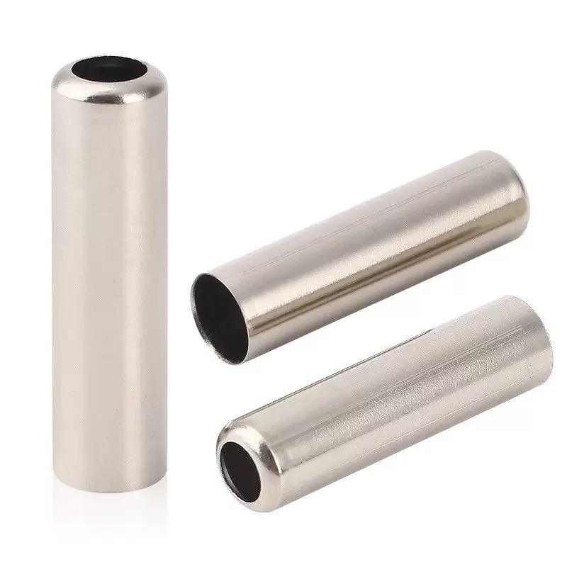
A round sleeve is a bearing surface, so the ID is the datum that matters
A deep drawn round sleeve looks like the simplest part in the catalogue, and that is exactly why it gets specified badly. A sleeve is not a tube that happens to be closed at one end; it is a bearing surface, and the surface that matters is the bore. The outer diameter is mostly there to give the press something to grip and the assembly something to hold, but the inner diameter is the datum the whole part is built around. When a drawing calls the OD as the primary dimension and leaves the ID as “as drawn,” we push back, because on a sleeve the ID is the feature that either runs in a bore or carries a shaft, and that is where the tolerance has to live.
We hold the drawn OD to +/-0.1 mm as the specification allows, but for any sleeve that seats or is seated, the ID is machined and held to +/-0.03 mm. The reason is geometric, not commercial: a drawn wall is never perfectly concentric to its own axis, because the blank feeds slightly off-center and the redraw magnifies the offset. If you dimension from the OD, every bore you cut is running on a moving centerline. If you dimension from the ID, the OD is allowed to float within its band and the fit is still true. So the first decision on a sleeve quotation is which surface is the datum, and for a bearing sleeve the answer is always the bore.
That decision also fixes the process order. We draw the shell to leave enough wall, then machine the ID on a turning center referenced to the OD so the bore is centered on the part as drawn, and only then do we treat the OD as a secondary check. A sleeve that is “drawn to size” on the ID alone will drift bore-to-bore; a sleeve that is machined from a drawn shell is a sleeve that fits.
Nickel plating adds to the ID, and that is where the fit lives
Nickel plating is what makes these sleeves corrosion resistant and, on the decorative grades, presentable, but it is also the dimension that most often breaks the fit. Engineering Watts nickel builds at a rate near 25 micrometres per amp-hour of current density, and a typical functional deposit runs 8 to 20 micrometres per side. That is 0.016 to 0.040 mm added to the bore on a part whose total ID tolerance may be 0.06 mm. Plate after machining and you have consumed two-thirds of the fit band in coating alone.
We handle this the way the fit demands: the bore is sized to the pre-plate dimension, the deposit is specified as a thickness class rather than “nickel plate,” and the finished ID is verified after plating, not before. If the customer needs a press fit on a plated sleeve, we calculate the interference on the plated bore, not the machined bore, because the shaft meets the nickel, not the steel. A slip fit is the same story in reverse: the plated ID must still clear the shaft with the deposit in place, so the pre-plate bore is opened by the full coating thickness plus the slip allowance.
The outer diameter is less sensitive, which is another reason the ID leads. We can let the OD take the full deposit and still hold the assembly fit, because the sleeve is usually pressed into a housing that is reamed to suit. So the plating thickness class is chosen for the bore, and the OD simply inherits it.
- Specify nickel as a thickness class, 8-20 micrometres per side, not as a finish name.
- Size the bore to the pre-plate dimension and verify the finished ID after plating.
- Calculate press and slip fits on the plated bore, because that is the surface in contact.
- Use the OD as the secondary datum; let it absorb the full deposit.
Drawing a thin-wall sleeve without collapsing the bore
The sleeves that give drawing trouble are the thin-wall ones, where the wall is a fraction of the diameter and the part wants to collapse the moment the punch clears the die. A 20 mm bore with a 0.6 mm wall is a 33:1 ratio, and at that aspect the redraw is the operation that fails, not the first draw. The wall buckles inward as it is pushed through the reducing die, and you get a sleeve that looks round until you drop a gauge in and watch it hang.
We control this with a mandrel draw for the thin-wall sizes. The shell is drawn over a fixed or floating mandrel so the bore is supported through the reduction, and the wall cannot fold because there is steel behind it. The cost is tooling complexity and a slower stroke, but it is the only way to hold a thin-wall bore round and on size. For thicker walls, 1.0 mm and above on a 20 mm bore, a conventional redraw with a well-tuned blank holder is enough, and we keep the blank holder force high enough to stop wrinkling without so high that it stretches the wall and tears at the nose radius.
The other lever is the blank. A sleeve that needs a 33:1 draw cannot start from a disc the LDR would forbid; we stage it through two or three reductions of 25 to 30 percent each, with in-line annealing where the work hardening has eaten the remaining ductility. The intermediate shells are handled between stages, and each stage is recorded as a setting against the part number so the window is not found twice.
Why we plate before the final sizing pass, not after
There is a tempting sequence on a nickel sleeve: draw, machine the ID, then plate, then ship. It fails in the bore. Plating throws unevenly into a blind or semi-blind sleeve, thicker at the mouth, thinner at the closed end, and if you machine the ID after plating you are grinding nickel off a surface that was supposed to be the corrosion layer, and you open the deposit to bare steel at the high spots. Worse, a post-plate bore cut leaves a step at the tool entry that traps coolant and seeds corrosion right where the sleeve lives.
Our sequence is draw to near size, plate to the specified class, then take a single light sizing or burnishing pass on the ID if the fit demands it, removing only what the deposit variation requires and never cutting through to base metal across the bore. Where the fit is generous we skip the final cut entirely and let the plated bore stand as deposited, verified by air gauge. The plating is therefore continuous and the fit is still met, which is the whole point of a nickel sleeve.
For the OD we are freer, because the sleeve is normally pressed into a housing reamed to suit, so the plated OD is accepted as drawn plus deposit and only spot-checked. The discipline is reserved for the bore, which is where the sleeve earns its keep.
Sleeve straightness over length and how we measure it without a fight
A sleeve is long compared to its diameter, and length is where straightness shows up. A 60 mm sleeve on a 20 mm bore will bow if the blank holder was uneven or if the redraw pushed one side harder, and a bowed sleeve jams in the housing or rings as it rotates. We hold straightness to a total band, typically 0.1 to 0.2 mm over the length for the sizes we run, and we measure it the unglamorous way: the sleeve is rolled in a V-block and an indicator is run along the OD, which is honest because the OD is the surface that contacts the housing.
The fight we avoid is measuring straightness on the bore. A bore gauge reads diameter, not axis, and inferring straightness from bore readings invites argument about which chord you happened to sweep. The V-block method gives a number both sides can agree on, and it catches the specific failure we care about: a sweep that bows the axis even when every diameter is in tolerance. When a sleeve fails straightness we do not re-cut it; we go back to the blank holder setting on the last draw, because that is where the bow was born.
We also watch earing. Rolled sheet draws with a four-lobed earing pattern, and on a long sleeve that pattern can read as a slow taper if the trim does not fully clean it. We trim the open end after the final draw and check height at four positions so a tapered sleeve is caught before plating, when it is still cheap to fix.
How we verify a plated ID against the press-fit specification
A nickel sleeve is judged on two things the customer cannot see: the bore after plating, and the deposit itself. The verification is written into the first article and audited on production, and it is what separates a sleeve that fits from one that gets reamed on the line.
- Bore diameter is measured after plating with an air gauge or a two-point bore gauge set to the plated ID limit, not the pre-plate limit, on every first article and on periodic production audit.
- Nickel thickness is confirmed by XRF on the bore and the OD, or by cross-section on a sacrificed piece, against the specified class of 8-20 micrometres per side.
- Adhesion is checked by a bend or heat-quench test on a witness strip from the same rack, because a sleeve that loses its nickel in service is a sleeve that rusts from inside.
- Straightness is rolled in a V-block with an indicator along the OD and compared to the total band on the drawing.
- Wall is ultrasonically checked at the nose radius on the first article so the thin spot is known before machining commits the bore.
- Material is traced to the mill certificate of the heat consumed, so the shipment packet documents the steel the sleeve was actually drawn from.
Send the drawing or a sample sleeve to measure, and the review returns the pre-plate bore we will hold, the nickel class, and the fit calc on the plated ID, so the sleeve that arrives is the sleeve that presses in.
Our deep drawn covers guide puts numbers to the design decisions behind a part like this — draw ratio, wall thinning, radii and trim; the Precision Deep Drawn Parts pages collect the rest of the family.
Specifications
| Item | Nickel Plated Steel Deep Drawn Round Sleeves |
|---|---|
| Brand | AUNOV |
| Designing | Send us your 2D drawing, or mail a sample for measurement, DFM feedback is returned with the quote. |
| Tooling | Our own toolroom designs and builds every die, held and maintained under your part number. |
| Samples | Approval samples of the sleeve ship with a full dimensional report and material certification. |
| Materials | Carbon steel (SPCC / DC01) leads the stock list for this part, alongside 304 / 316 stainless steel, aluminium, brass and copper, with grade selection confirmed at drawing review. |
| Surface finish | Your print chooses between plating, e-coat, powder coating, anodising or passivation. |
| Processing | Progressive deep draw stages with in-line annealing as the draw ratio demands, then pierced and CNC-machined in house. |
| Equipment | 5-250 T mechanical presses plus 250-500 T hydraulic presses, CNC turning and milling cells, a climate-controlled CMM room. |
| Tolerance | Drawn tolerances held to +/-0.1 mm, +/-0.03 mm on machined surfaces. |
| Delivery terms | FOB standard, DDP offered for EU and US, T/T or L/C, with D/P for repeat business, call-off scheduling supported. |
Frequently Asked Questions
Why is the bore the datum on a deep drawn sleeve?
A sleeve is a bearing surface, and the surface that matters is the bore – it either runs in a bore or carries a shaft, while the outer diameter mostly gives the press something to grip. When the bore is the datum, the fit stays true even as the OD floats within its band; dimensioning from the OD instead puts every cut bore on a moving centerline.
How is a thin-wall sleeve drawn without collapsing the bore?
The shell is drawn progressively with in-process checks, then plated before the final sizing pass rather than after, so the plating adds to the bore and the sizing pass sets the fit. The bore is then machined to its band, which keeps a thin wall from collapsing during the operation that matters.
What tolerance holds the ID of a plated sleeve?
The inner diameter is machined and held to a few hundredths of a millimetre, while the as-drawn outer diameter is held to a looser band, because the ID is the feature that seats. The plated ID is verified against the press-fit specification on the CMM at first article.
Why nickel plate a deep drawn steel sleeve?
Nickel builds the bearing surface and the corrosion resistance on the inner diameter where the fit lives, and plating before final sizing means the plated bore is sized true rather than cut after the fact. It is specified for the service the sleeve sees, not for appearance.
Related Products



Request a Quote for This Part
Send a drawing or sketch — get material advice, tooling cost and a per-piece price within 24 hours (working days).