
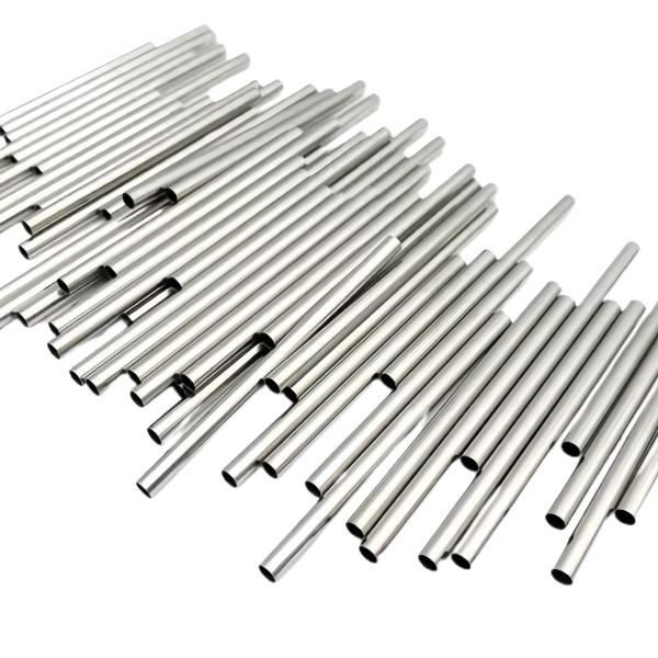
A bundle is a product where variation between tubes matters as much as within one
A capillary tube bundle is not a tube with a quantity. It is an assembly whose function – parallel flow distribution, heat exchange area, chromatography separation, sample conditioning – depends on dozens of small tubes behaving identically, and that makes the population of tubes the specification, not the individual part. A bundle can be built from tubes that each pass their own dimensional check and still fail as a bundle, if one tube runs 10 percent faster than its neighbours or one bore is partially blocked at the brazed end.
The bundle-level quantities that have to be specified, and that a single-tube drawing has no place to put:
- Flow uniformity across the bundle: the spread between the fastest and slowest tube, expressed as a percentage of the mean. This is the bundle’s core figure of merit for flow-duty bundles, and it is the number that drives our bore-tolerance and flow-matching decisions upstream.
- Pitch and parallelism: the tubes’ positions in the bundle – the spacing that lets fluid or air sweep between them, and the alignment that lets both ends enter their headers. A bundle that looks straight in the fixture and walks out of position at the far end is a bundle that cannot be headered.
- Tube count and interchangeability: whether the bundle treats its tubes as identified positions (each tube has a role, a flow class and a serial number) or as interchangeable channels (any tube could be any channel). The verification burden differs by a factor of the tube count.
Why we pull a whole bundle’s bores from one melt
The single most effective thing we do for bundle uniformity happens before any tube is drawn: the entire bundle starts as one heat of steel. One melt means one chemical analysis, one rolling schedule, one anneal history at the mill, and therefore material that work-hardens, draws and springs back identically through every pass. Two melts of nominal 304 with analyses at opposite ends of the allowed range draw differently enough to matter: the bore a plug produces in a harder melt is a few microns different from the same plug in a softer melt, and across a bundle that is spread between tubes before the flow test ever runs.
What melt discipline buys, concretely:
- Uniform drawing behaviour: every tube in the bundle takes the same pass schedule to the same final dimensions, so the bore population is tight around the target and the flow spread follows.
- Uniform response at the braze or weld: all the tubes in the bundle move the same way under the header-joining heat, so the bundle’s alignment survives joining. A mixed-heat bundle can walk at the ends because one group of tubes relaxed its residual stress at a slightly different rate.
- A single certificate story: the whole bundle carries one melt number, one material certificate, one PMI record – which for the customer’s own documentation is dramatically simpler than a bundle with three heats in it.
Aligning dozens of small tubes: pitch tolerance and the header plate
A bundle’s geometry is set by its headers – the plates, blocks or fittings that hold all the tube ends in their positions – and the bundle manufacturing question is how the tubes stay located between the headers through cutting, joining and handling. Below roughly 3 mm tube OD, a capillary bundle cannot be held pitch-perfect by hand or fixture alone over a long length; the bundle has to be assembled progressively, and the pitch tolerance has to be set by what the assembly sequence can actually hold.
The assembly routes, and the pitch realities of each:
- Header-plate assembly (the standard route): tubes are inserted through drilled or laser-cut holes in both end plates, the plates are jigged at final spacing, and the bundle is tensioned straight. The plate hole pitch is machined to position, typically +/-0.05 to +/-0.1 mm on a plate jig-drilled or laser-cut in one setup, and the tubes follow the plates. Between the plates, a bundle of soft capillaries needs spacers or a periodic wrap to stop the tubes touching and vibrating against each other – and the drawing should say whether inter-tube contact is acceptable or must be prevented, because that decision changes both the assembly and the in-service behaviour (touching tubes wear at the contact points under vibration; spaced tubes have their own acoustic and thermal character).
- Braze-in-header assembly: tubes enter a header block, are brazed in place, and the block’s own machining sets the pitch. Tighter pitch control (the block is machined, not drilled in situ), at the cost of a joining step whose heat can move everything – which is why the block’s fixturing during brazing is part of the process design.
The header-plate question that most drawings leave open: who makes the plate? The plate’s hole pattern, hole diameter class (clearance for insertion, then fill by braze or potting) and material all interlock with the tubes’ diameter tolerance and the joining method. Where the customer supplies plates, we ask for the plate drawing with the tube drawing – the pair is the product, and our fixture is built to the pair. Where we make the plates, the quotation lists them and the tolerance stack between plate pitch and tube OD is our problem, stated in the review.
Joining the ends without blocking a single bore
The joining operation is where capillary bundles live or die. Every tube end has to be joined to its header – brazed, welded, or potted – and the joint has to seal the annulus around a bore that is measured in tenths of a millimetre. A braze alloy that wicks a fraction of a millimetre too far closes a capillary bore permanently, and a bundle with one blocked channel fails its flow test and has to be re-opened or scrapped, which is why the joining method is chosen with the bore size on the table.
The methods and their capillary logic:
- Vacuum or controlled-atmosphere brazing is the default for stainless steel bundles: filler pre-placed as rings, foils or paste at each tube end, the whole assembly heated uniformly in one cycle, and all joints made simultaneously. Capillary rise of the filler is a physical property of the joint geometry – gap, cleanliness, filler volume – and it is controlled by design: the header holes are sized to a nominal braze gap, the filler is metered per joint, and the bore entrance is kept out of the filler’s path by geometry (a counterbore or a stop that keeps the alloy a defined distance from the bore mouth). We section first articles to confirm the filler stopped where the design says.
- Laser welding joins tube to header with no filler at all, which removes the bore-blocking risk entirely and is the right answer for bores under 0.5 mm where a braze cannot be trusted. The trade is cycle time: joints are made one at a time, and a 60-tube bundle is an hour of welding against minutes of brazing. Hybrid bundles (laser for the smallest bores, braze for the rest) exist and quote as the sum of their processes.
- Potting (epoxy or other resin) seals by filling the interstices, and it is the low-cost route for bundles whose temperature and chemistry allow it. The bore is protected by inserting the tubes through the plate with a masked standoff, so the potting depth stops short of the bore mouth; the resin’s cure shrink and thermal expansion are matched against the bundle’s service range in the review, because a potted bundle that sees 150 degrees C needs a resin chosen for it.
The bundle’s environment decides the grade, not the single tube’s
304 is the bundle’s default grade and the right one for the majority of services – clean gases, water-adjacent duty, food-safe contact, most laboratory and instrument work. But a bundle exposes far more material to the environment than a single tube does: the total wetted or exposed surface is the tube count times the length times the circumference, plus the headers and the joints, and the environment attacks the whole assembly, including the crevices between tubes and the joint zones where filler and parent metal meet.
The grade decisions that bundles actually turn on:
- Chloride exposure: a bundle in a chloride-bearing environment – marine, coastal outdoor, brackish cooling, certain process streams – is a stress-corrosion risk multiplied by the tube count, and the answer is 316L across the bundle, headers and filler included. The cost delta of 316L over 304 on capillary stock is small at the tube sizes involved; the cost delta of replacing a corroded bundle is the whole assembly. We quote 316L as standard for any stated coastal or brackish service.
- Header galvanic compatibility: a 304 bundle brazed with a nickel-bearing filler into a brass or carbon-steel header is a galvanic pair with the headers as the anode, and in a wet service the header corrodes preferentially – sometimes by design, often not. The review checks the header material against the tube material and states the pair’s behaviour where the drawing leaves the choice to us.
How we verify a bundle by flow, not just by dimensions
Bundle verification is deliberately functional-first, because the dimensions are a means and the flow behaviour is the end. The sequence, run per bundle:
- Tube-level verification before assembly: every tube’s bore gauged (pin or air gauge at both ends), OD measured at stations, and for flow-critical bundles every tube flow-checked individually against the flow class. Individual flow records are what make the bundle’s population claim auditable.
- Population statistics reported: mean flow, standard deviation, and max-min spread across the bundle’s tubes – the figures the uniformity specification is written against, reported per bundle for identified-position bundles and per lot sample otherwise.
- Post-assembly channel test: every channel of the finished bundle flow-tested after joining, against the acceptance band, which is the check that catches a blocked bore or a compromised joint – the two failure modes that exist only after assembly.
- Leak test where the duty demands it: pressure decay, immersion or helium per the drawing, on 100 percent of pressure-duty bundles, hold time stated.
- Geometric verification: header pitch against the plate drawing, bundle straightness and length on the surface table, and end-face condition – square, flush, and free of joint spatter or potting flash over any bore mouth.
- Sectioned first article of a joint: one joint from the first bundle cut and examined for filler depth, bore clearance and fillet quality, which calibrates the joining process for the run.
- Material certificate set: mill certificate for the melt, PMI records, filler and header lot records, and the bundle’s individual and post-assembly flow records – shipped as one package, per bundle, so the serial number on the assembly traces to the melt it came from.
Send the drawing or a sample bundle, plus the header drawing if you have one. The review that returns with the quotation states the tube count, bore class, flow uniformity band, joining method, header plan, material grade with the environment it assumes, and the per-bundle verification list – the whole bundle specified as what it is: an assembly whose quality is measured across its population.
This part belongs to our Deep Drawn Tubes & Sleeves range. The deep drawn tubes & sleeves pages collect the process notes, common materials and inspection points behind every product in the family.
Specifications
| Item | Stainless Steel Capillary Tube Bundle 304 Grade |
|---|---|
| Brand | AUNOV |
| Designing | Share your print, or send a part to be measured, you get a DFM review together with the quotation. |
| Tooling | Tooling designed and cut in house, held and maintained under your part number. |
| Samples | First articles go out with a dimensional report and material certification. |
| Materials | 304 / 316 stainless steel is the primary stock for this part, alongside carbon steel (SPCC / DC01), aluminium, brass and copper, and the grade is fixed at the drawing review. |
| Surface finish | Plating, e-coat, powder coating, anodising or passivation, exactly as your print calls for. |
| Processing | Staged deep drawing with in-line annealing where needed, pierced and finish-machined on the same floor. |
| Equipment | Press capacity from 5 to 500 T across mechanical and hydraulic lines, CNC turning and milling cells, a climate-controlled CMM room. |
| Tolerance | Drawn tolerances held to +/-0.1 mm, +/-0.03 mm on machined features. |
| Delivery terms | FOB is standard; DDP offered for EU and US, T/T and L/C; D/P on repeat accounts, call-off scheduling supported. |
Related Products


Request a Quote for This Part
Send a drawing or sketch — get material advice, tooling cost and a per-piece price within 24 hours (working days).