
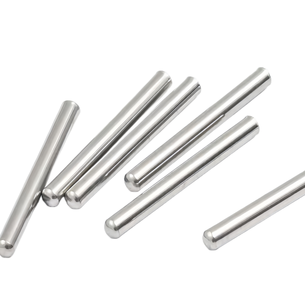
The Stainless Steel 304 Precision Capillary Tube is defined by one number: the bore. On this page we get specific about how a 0.6 to 3 mm bore is actually held to ±0.02 mm, why cut-off and cleanliness dominate field failures, and what a capillary shipment file must contain for the bore to be trusted without re-measurement at your dock.
Holding a small bore to ±0.02 mm: plug drawing versus drilled stock
There are only two honest ways to make a precision small bore in stainless steel, and the choice sets the whole cost structure. Drilling starts from bar, puts a twist drill through a solid section, and works – but drill wander in a deep, small-diameter hole is unforgiving: past a depth of roughly five diameters, drill drift is measured in tenths of millimeters, drill breakage eats cycle time, and the bore finish is a spiral that no one callouts as Ra but everyone measures as flow variation. For capillary work we therefore draw the bore, not drill it.
Plug drawing inverts the problem. The bore is generated by a polished carbide or tool-steel plug whose diameter is ground to the bore tolerance, and the tube is pulled through a die ring over that plug. The bore is as accurate as the plug, and a plug is a shape we can lap to ±0.003 mm and inspect on a bench without any of the in-process guesswork that a deep drill demands. The staging is what makes it production-viable:
- First draws size the tube down in stages with generous reduction – around 20 to 25 percent per pass for 304 in the annealed condition – with the plug only introduced once the wall has stabilized, so plug wear is not spent fighting blank scatter.
- Intermediate anneals between stages restore ductility; 304 work-hardens fast, and skipping an anneal shows up immediately as a torn bore on the next pass.
- The final pass is a light sizing pass at under 5 percent reduction, run slowly with a fresh plug surface, purely to lock the bore diameter and inner finish.
The practical ceiling on bore accuracy is then plug-to-bore elastic recovery: the tube springs open slightly as it leaves the die, by an amount that depends on wall thickness and reduction. We establish the exact springback for each tooling set on the first article, grind the plug to compensate, and archive that offset against the part number so the tooling reproduces itself on reorders.
Bore tolerance is a flow-control requirement, not a dimension
Capillaries exist to restrict or meter flow, and the arithmetic is brutal. Flow through a small bore scales with diameter to the fourth power. A bore that varies by ±0.02 mm on a 1.00 mm nominal is a ±2 percent diameter band – and a ±8 percent flow band before any upstream pressure tolerance enters. If the assembly is a metering orifice in a refrigerant circuit, a thermowell filler tube, or a medical lumen, the part has to be treated as a flow device, and we encourage customers to specify the bore in terms of both the diameter band and a flow acceptance test where the fourth-power sensitivity is real.
The flow test itself is not exotic: constant pressure head, temperature-stabilized water or calibrated oil, timed volume. What makes it useful is running it against the boundary parts of the bore tolerance, not the nominal – if the flow acceptance is proven on parts deliberately drawn at the small and large ends of the bore band, then the whole bore band is flow-safe, and production gauging can stay dimensional rather than hydraulic. On capillary programs where the customer lacks a flow bench, we build this boundary proof into the first article so the burden never lands on your receiving dock.
One second-order effect worth naming because it bites silently: bore roundness. An oval bore at the same average diameter flows differently from a round one, and a plug-drawn bore inherits the plug’s roundness, which is why our plug inspection includes roundness on a measuring projector, not just size on a micrometer.
Cut-off, burrs and the invisible contamination problem
Field failures on capillary tube are almost never drawing failures. They are cut-off failures: a burr partially occluding the bore, a smear of smeared metal folded into the entrance, or a chip that broke free during a later handling step and lodged somewhere it cannot be flushed out. A burr of 0.05 mm on a 0.6 mm bore is an 8 percent flow obstruction that no end user will ever see and every system will feel.
The countermeasures are process choices, in this order:
- Cut method matched to bore size. Abrasive cut-off under flood coolant below about 1.5 mm OD, where the wall is too thin for a clean shear; supported shear above that, which is faster and leaves a burr-free face when the blades are dressed.
- Burr removal that reaches the entrance. Chamfering the bore edge with a small carbide cutter or abrasive-filled wire, so the transition into the bore cannot shave or hold anything.
- Flushing as a routing step, not a courtesy. Every capillary gets a high-pressure flush – alternating solvent and filtered air – after final cut, in a fixture that points the flush stream through the bore rather than around it.
- A cleanliness acceptance test. We pass a calibrated wire gauge or filtered fluid through every part in the sample plan; a part that passes a gauge pass has a provably clear bore, not a visually probably-clear one.
The gauge pass is the step we would refuse to drop in a cost conversation. It is minutes per thousand parts, and it is the difference between a cleanliness claim and a cleanliness proof.
Annealing, straightness and handling on long lengths
Capillary is frequently supplied in lengths measured in hundreds of millimeters to a few meters, and the length-to-diameter ratio changes the failure modes. A drawn tube with a 100:1 ratio will not stay straight on its own; residual hoop and axial stresses from the sizing pass relax over days, and coiling for annealing or transport adds set that has to be removed afterwards. We anneal capillary in straightened fixtures whenever the print demands a straightness band, and we handle it in rigid trays between operations – a capillary thrown loose into a bin develops bends that are cosmetic to fix and dimensional to ignore at your peril.
Where the application genuinely needs dead-straight long capillary, we quote straightened-and-cut lengths rather than coil, and we flag the handling implication explicitly: a 600 mm capillary at 0.4 mm wall will take a permanent set from a careless grip, and packaging has to enforce that reality rather than pretend otherwise. Our standard pack for long capillary is a rigid tube with end caps, one part per channel, with the bore protected by end plugs that also serve as a tamper indicator.
Material condition is the final lever. Full anneal leaves the capillary soft and easy to form in your next operation but with a slightly less stable shape; partial stress-relief keeps the tube harder and straighter but transfers forming effort downstream. The right answer depends on whether your assembly bends the capillary – a thermowell does, a welded-in orifice does not – and it is a drawing note, not a shop preference.
How we verify bore, cleanliness and length on capillary batches
The verification file for capillary is built around the premise that your dock should never have to re-measure what we already proved:
- Bore diameter – plug gauge go/no-go at the drawing tolerance band, plus measured bore on the sample plan using pin gauges stepped to 0.005 mm, recorded per part on the first article and per sampling plan in production.
- Bore roundness and finish – section check on the first article with projected roundness and Ra measurement in the bore; production sections at a defined frequency tied to plug changes.
- Flow acceptance – where specified, timed-volume flow tests at stabilized temperature on boundary-tolerance parts, with the test parameters archived so your calibration can reproduce them.
- Cleanliness – gauge-pass proof on every part in the sample plan after final flush, plus gravimetric residue checks on a defined frequency for programs with a particulate limit.
- Length and end condition – cut length verified against a hard stop, end squareness and chamfer confirmed at 10x, and the flush-and-plug sequence recorded in the routing so the closed bore at your dock is provably as-shipped.
- Traceability – coil certificate, annealing lot, and plug identity all archived against the lot number under our ISO 9001 system, so a reorder reproduces the proven configuration.
Send the drawing with the flow requirement stated, and the first article will come back with bore, flow and cleanliness demonstrated on the same parts you can then use as masters.
Deep Drawn Tubes & Sleeves is the parent range for parts like this one; the overview page gathers the tooling logic, finishing options and tolerance notes that apply across the family.
Specifications
| Item | Stainless Steel 304 Precision Capillary Tubes |
|---|---|
| Brand | AUNOV |
| Designing | Send drawings, or send a tube sample to be measured, our engineers reply with a manufacturability assessment and pricing. |
| Tooling | Every die designed and built in our toolroom, stored under your part number. |
| Samples | Sample parts arrive with a dimensional report and material certificate. |
| Materials | 304 / 316 stainless steel is the primary stock for this part, alongside carbon steel (SPCC / DC01), aluminium, brass and copper, per the drawing. |
| Surface finish | Plating, e-coat, powder coating, anodising or passivation as the drawing calls out, selected against the drawing requirement. |
| Processing | Staged deep drawing, with in-line annealing where the draw ratio requires, with piercing and finish machining under the same roof. |
| Equipment | Our press floor runs 5-250 T mechanical and 250-500 T hydraulic presses, in-house CNC cells and a temperature-controlled inspection room. |
| Tolerance | Drawn tolerances held to +/-0.1 mm, with machined features to +/-0.03 mm. |
| Delivery terms | Standard terms FOB, DDP offered to EU and US, T/T and L/C; D/P on repeat accounts, scheduled call-offs welcome. |
Related Products



Request a Quote for This Part
Send a drawing or sketch — get material advice, tooling cost and a per-piece price within 24 hours (working days).