
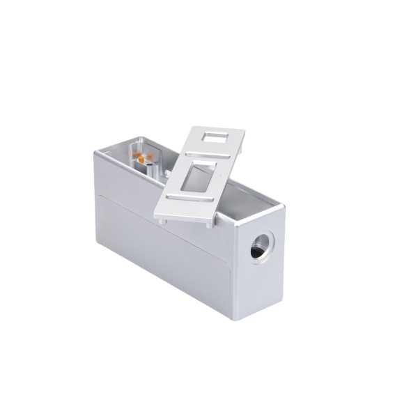
The side port on an enclosure changes the stress pattern of the whole wall it penetrates
An enclosure with a side port—a cable or fluid access hole in one wall—is a plate with a hole, and a hole in a pressurized or loaded wall concentrates stress at its edge by a factor of ~3. If the enclosure is sealed and pressurized (washdown enclosures, outdoor junction boxes with solar heating, fluid-tight housings), the port’s edge is where the wall cracks first under cyclic pressure.
We machine side ports with two features that manage this: a generous edge radius (R ≥ 1 mm on the port’s rim, larger for ports above 25 mm diameter) which drops the stress concentration factor from 3.0 toward 1.5, and a thickened pad around the port when the port carries a fitting or connector (the fitting’s clamp load and the cable’s bending moment both react at the port edge—local thickness spreads them).
Port sealing method sets the enclosure’s IP rating more than the enclosure’s seams do
Enclosure seams (lid-to-body) are engineered by the enclosure industry and generally reliable. The ports are where field assemblies leak: every port is a hole that someone seals at installation time, with varying skill. The three architectures, in ascending reliability:
- Open port + field-installed gland: We machine the hole; the installer fits a cable gland. The seal quality is entirely in the installer’s hands (gland selection, torque, cable diameter match). We print the port’s diameter tolerance on the drawing so the gland can be selected to match—glands are specified for cable diameter ranges, and the port hole must match the gland’s thread, not the cable.
- Machined gland seat: We machine a seat for a specific gland family (a counterbore plus thread, with the seat face flat within 0.02 mm). The gland’s seal (an O-ring under its nut) seats against our machined face. Far more repeatable than open-port sealing; the installer can only get it right.
- Integral molded seal port: For high-volume enclosures, a port design with a molded elastomer membrane (a flat diaphragm with cross-cuts) that seals around each cable by elastic grip. No installer dependence at all; the membrane’s IP rating is certified with the enclosure. We machine the membrane’s retaining features and verify the membrane compression (the retainer’s depth holds the membrane at its designed 20–30 % squeeze).
Enclosure wall thickness at the port, under the fitting’s nut, must survive clamp load
The fitting or connector at the port tightens against the wall from outside, pulling with full thread torque. Thin-walled enclosures (1.5–2.5 mm aluminum) locally deform under a hardened nut’s edge load—the wall dimples, the seal relaxes, and the joint weeps after thermal cycling.
We address this with a machined reinforcement pad around every port on thin-wall designs: the pad raises local thickness to 4–5 mm over a footprint 1.5× the fitting’s nut diameter. The pad blends into the wall with a 45° chamfer (not a sharp step, which looks unfinished and creates its own stress concentration). Where the enclosure’s exterior must remain flush (sliding installations, appearance-critical products), the pad is machined into the interior instead—same clamp-load spreading, invisible from outside.
Conductive continuity across the port for EMC-shielded enclosures
When an enclosure is an EMC shield (electronics housings with shielding requirements), every port is a hole in the shield, and the shield’s effectiveness is set by the port’s treatment. An unmaintained port (a plain hole with a plastic gland) radiates through the aperture; the shielding effectiveness of an enclosure with even one 20 mm uncontrolled port can drop by 30–40 dB.
For shielded enclosure designs, we machine ports for shielded connectors (metal-shell connectors with 360° contact to the enclosure wall) and maintain the conductive path by masking the port’s contact surfaces during anodize (anodize is an insulator, as noted for our mounting bases). The contact band around the port—where the connector’s shell grips the wall—is left bare aluminum, verified with a milliohm meter from the port’s contact surface to the enclosure’s designated ground point: < 5 mΩ acceptance.
How we verify ported enclosures before shipping
- Port geometry: Diameter (go/no-go or bore gauge), seat flatness where seats are specified (0.02 mm), thread class where ports are threaded.
- Port position: Relative to enclosure datums, ±0.2 mm standard; verified with a height gauge or CMM on first article.
- Seal test (if IP-rated): Enclosure closed with its lid, ports sealed with production-equivalent plugs or the specified gland, then tested to the IP rating: IP65 water-jet, IP67 1 m/30 min immersion. Moisture-detecting paper inside confirms zero ingress.
- Pressure test (if pressure-rated): 1.5× rated pressure for 10 minutes; watch the port edges specifically—stress-cracked port rims weep first, and a weeping rim means the pad design or the radius was underdone, a design finding rather than a part rejection.
- Shield continuity (if EMC): Port contact band to ground point < 5 mΩ; lid-seam continuity verified across the gasket's contact fingers.
CNC Machining Parts is the parent range for parts like this one; the overview page gathers the tooling logic, finishing options and tolerance notes that apply across the family.
Side-port seal under pressure
An enclosure with a side port breaks the continuous wall, and that break is the first place it leaks, so the port is sealed as a joint, not as an afterthought. We draw the port boss concentric to its bore and we specify the gasket or O-ring so the clamp load seats it without crushing the thin aluminum around it. The thread that holds the port fitting is kept clear of the seal face so make-up torque does not distort the seat, and we verify the seal at pressure, not just at hand-tight, because an enclosure that weeps only when the system is live is the one that fails in the field.
EMI gasket channel machined into the lid
Where the enclosure shields a signal, the lid seam is the leak, and we machine a continuous gasket channel into the lid so the EMI gasket has a home instead of being squeezed wherever it lands. The channel is sized to the gasket so it compresses the right amount around the whole perimeter, including the corners where shields usually break. We hold the channel depth and continuity because a gap of a few millimeters is all a high-frequency signal needs to escape, and the shield is only as good as its worst corner.
Specifications
| Item | Aluminum CNC Machined Enclosure with Side Port |
|---|---|
| Brand | AUNOV |
| Designing | Send us your 2D drawing, or mail a sample for measurement, our engineers reply with a manufacturability assessment and pricing. |
| Tooling | Dies engineered and produced in our own toolroom, held under your part number. |
| Samples | Sample parts arrive with a dimensional report and material certificate. |
| Materials | Stock for this part leads with aluminium, alongside carbon steel (SPCC / DC01), 304 / 316 stainless steel, brass and copper, per the drawing. |
| Surface finish | Plating, e-coat, powder coating, anodising or passivation as the drawing calls out, per your print. |
| Processing | Progressive deep draw stages with in-line annealing as the draw ratio demands, pierced and machined on the same floor. |
| Equipment | Press capacity from 5 to 500 T across mechanical and hydraulic lines, CNC turning centres and a climate-controlled CMM room. |
| Tolerance | Drawn tolerances held to +/-0.1 mm, +/-0.03 mm after machining. |
| Delivery terms | FOB standard, DDP offered for EU and US, T/T or L/C, with D/P for repeat business, call-off scheduling supported. |
Related Products


Request a Quote for This Part
Send a drawing or sketch — get material advice, tooling cost and a per-piece price within 24 hours (working days).