
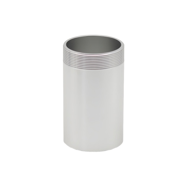
Large-diameter thread machining accuracy determines whether a cylinder sleeve seals without a gasket
A large aluminum threaded cylinder sleeve—typically above 80 mm thread diameter—uses its thread to pull a cap or end plate against a seal. At this size, thread machining accuracy directly affects the seal’s compression and the assembly’s alignment.
The challenge with large threads is the ratio of pitch-diameter tolerance to thread diameter. An M100 × 2 thread has a 6g tolerance band of roughly 0.05 mm on pitch diameter—proportionally tighter than an M10 × 1.5 (band ~0.11 mm on a much smaller diameter). Holding this requires rigid setups, sharp tools, and careful attention to thermal growth of the workpiece during cutting. A 30 °C temperature rise in a 100 mm diameter aluminum sleeve expands the thread by 100 × 23 × 10⁻⁶ × 30 = 0.07 mm—larger than the entire tolerance band. We compensate by cutting large threads with coolant flood, measuring the actual thread diameter at machine temperature, and applying a correction offset based on the measured workpiece temperature.
Thin-wall deflection during threading is the main source of ovality in large sleeves
A large aluminum sleeve with a wall thickness of 5 mm on a 100 mm bore is flexible: its radial stiffness is low enough that chucking forces alone can ovalize it by 0.05–0.10 mm. If the thread is cut while the sleeve is ovalized (from chuck pressure), it relaxes to round when unclamped—but the thread becomes oval (larger pitch diameter on one axis, smaller on the other).
We prevent this by using expanding internal mandrels or six-jaw chucks that distribute clamping force uniformly, rather than three-jaw chucks that concentrate force at three points. For sleeves too large for our largest mandrel, we thread between centers using a driving dog (no radial clamping at all) or use a soft-jaw wrap-around chuck that grips over 180°+ of circumference. After threading, we verify roundness with an inside micrometer at three angular positions; acceptance is 0.02 mm TIR ovality for sleeves that will seal through a compliant gasket, 0.01 mm for metal-to-metal seal designs.
Sleeve-to-housing fit (if the sleeve inserts into another component) requires attention to CTE mismatch
When an aluminum sleeve fits inside a steel or cast-iron housing, the aluminum expands roughly 2× more per degree of temperature change (23 vs. 11–12 µm/m·K). A sleeve that is a light press-fit (0.02 mm interference) at room temperature becomes a slip-fit at 50 °C temperature rise on a 100 mm diameter: 100 × 11 × 10⁻⁶ × 50 = 0.055 mm of interference lost—converting 0.02 mm interference to 0.035 mm clearance.
We handle this in one of three ways: (a) increase the room-temperature interference to 0.06–0.08 mm so the joint remains tight at maximum operating temperature (requires thermal assembly: heat housing, chill sleeve); (b) add a mechanical retention feature (key, pin, or flange) that holds the sleeve axially regardless of fit; (c) change the sleeve material to match the housing CTE (steel sleeve in steel housing, or a composite sleeve with intermediate CTE). Option (a) is the most common for large cylinder sleeves in hydraulic service; option (c) is the most expensive but eliminates the issue entirely.
Anodize on the sleeve threads provides both corrosion protection and anti-galling benefit
Large aluminum threads, like stainless steel threads, are prone to galling during assembly—particularly when the same threads are assembled and disassembled multiple times (for maintenance access to the cylinder’s internal components).
Hard anodize (Type III, 25–50 µm) on the sleeve threads provides two benefits: the oxide layer (hardness 400–500 HV) is much harder than the aluminum substrate and resists the asperity deformation that initiates galling; and the oxide’s porous microstructure retains lubricant or anti-seize compound, further reducing friction during assembly. The anodize layer adds thickness (about half the coating thickness builds outward), so we machine the threads 10–25 µm undersize on pitch diameter before anodizing to hit the final class after coating. We verify post-anodize thread fit with go/no-go gauges; any part that gauges tight is re-machined (chased with a single-point tool to remove 5–10 µm of coating locally) before shipping.
How we verify a large threaded sleeve before shipping
Final inspection for large cylinder sleeves:
- Thread fit: Go/no-go ring gauge (external thread) or plug gauge (internal). For threads above 100 mm diameter where standard gauges are not available, we use a CMM with a stylus scanned along the thread helix to measure effective pitch diameter, or we mate with a master component (the actual cap or housing, if supplied) and verify smooth engagement.
- Bore size and roundness: Inside micrometer at three axial positions × three angular orientations. Acceptance: bore within H8 tolerance and ovality < 0.02 mm (or per drawing).
- Concentricity of bore to thread: Sleeve mounted on a thread-mandrel (or between centers via thread centers), bore runout measured with dial indicator. Acceptance: 0.03 mm TIR for standard sleeves, 0.015 mm for precision (bearing-carrying) sleeves.
- Surface finish: Bore Ra ≤ 0.8 µm (for seal sliding surfaces) or ≤ 1.6 µm (for non-sealing). Verified with stylus instrument on first article and every 20th part.
- Seal test (if pressure-rated): Sleeve assembled with its cap and seal, hydrostatic test at 1.5× design pressure for 10 minutes. Acceptance: zero leakage at the seal and thread interfaces.
This part belongs to our CNC Machining Parts range. The cnc machining parts pages collect the process notes, common materials and inspection points behind every product in the family.
Holding roundness on a long thin sleeve
A large threaded cylinder sleeve is long, thin, and wants to go oval the moment it is machined free of its bar, so we fixture it on its own axis with steady rests and we take light, symmetric cuts so the wall does not deflect under the tool. The roundness is checked on a mandrel or in a V, not by a caliper across two points, because a thin sleeve reads round to a caliper and ovals on the bench. We let the part settle between rough and finish and we measure after, because the roundness that matters is the one it has when installed, not the one it had under the steady rest.
Thread relief and the stress riser
The thread on a thin sleeve ends somewhere, and that ending is a stress riser if it is a sharp runout into a full wall. We put a relief or a gradual taper at the thread end so the load tapers off instead of concentrating at a corner, because a sleeve that cracks at the last thread is a sleeve that was detailed without the load path in mind. The relief is sized to the thread and the wall so it removes the riser without weakening the section, which is a small feature that decides whether the sleeve survives its own torque.
Specifications
| Item | Large Aluminum CNC Machined Threaded Cylinder Sleeve |
|---|---|
| Brand | AUNOV |
| Designing | Send the drawing, or a sample we can measure, you get a DFM review together with the quotation. |
| Tooling | Every die designed and built in our toolroom, each die held against your part number. |
| Samples | The first-article set ships with dimensional data and material certs. |
| Materials | Stock for this part leads with aluminium, alongside carbon steel (SPCC / DC01), 304 / 316 stainless steel, brass and copper, and the grade is fixed at the drawing review. |
| Surface finish | Plating, e-coat, powder coating, anodising or passivation, selected against the drawing requirement. |
| Processing | Staged deep drawing with in-line annealing where needed, then pierced and machined in house. |
| Equipment | On the press side, 5-250 T mechanical and 250-500 T hydraulic; CNC turning centres and a climate-controlled CMM room complete the floor. |
| Tolerance | +/-0.1 mm on as-drawn features, with machined features to +/-0.03 mm. |
| Delivery terms | Prices FOB, with DDP for EU and US on request, T/T or L/C, with D/P for repeat business, scheduled call-offs welcome. |
Related Products


Request a Quote for This Part
Send a drawing or sketch — get material advice, tooling cost and a per-piece price within 24 hours (working days).