
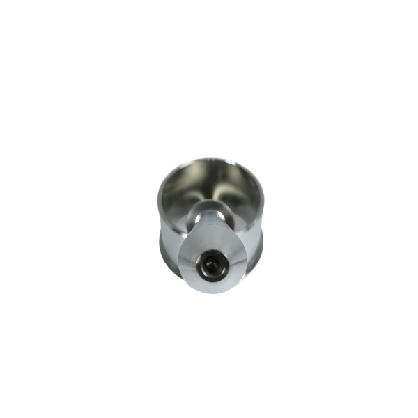
Dome-nozzle geometry combines two challenges: pressure containment and spray pattern formation
A dome nozzle housing—whether it is part of a fuel injector, a spray paint nozzle, or an industrial atomizer—must simultaneously contain internal pressure (often 5–30 MPa for fuel injection, 0.3–1.0 MPa for industrial spraying) and shape the fluid into a controlled spray pattern as it exits the orifice. These two functions compete geometrically: a thick-walled dome is good for pressure containment but adds mass and thermal inertia that affects cold-start performance; a thin-walled dome responds quickly to temperature changes but requires higher-strength material to contain the same pressure.
For stainless steel dome housings (the material specified for this product), we use 316 or 17-4 PH depending on the pressure rating. For pressures below 10 MPa, 316 in the annealed condition (yield ~205 MPa) with a wall thickness of 2–3 mm provides a safety factor of 3–4× at design pressure with respect to yielding. For pressures above 10 MPa (common-rail diesel injection, hydraulic atomization), we switch to 17-4 PH in the H900 condition (yield ~1170 MPa) which allows wall thicknesses of 1–1.5 mm while maintaining the same safety factor—critical for applications where the nozzle must heat up quickly during engine start.
The swirl chamber inside the dome is what creates the spray cone—not the exit orifice
In most dome-type nozzles, the spray pattern is not determined by the shape of the final orifice but by the upstream swirl chamber—a helical or tangential passage that imparts angular momentum to the fluid before it reaches the orifice. As the fluid approaches the orifice, the tangential velocity component forces it toward the walls of the orifice entrance, forming a hollow conical sheet that breaks up into droplets downstream. The cone angle is determined by the ratio of tangential to axial velocity at the orifice entrance, which is set by the swirl chamber geometry (inlet area, swirl radius, and chamber length).
We machine the swirl chamber using a 5-axis simultaneous machining operation that cuts the helical passage in a single pass with a ballnose end mill whose radius matches the designed channel curvature. The critical dimensions are the inlet port diameter (tolerance ±0.01 mm because it sets the mass flow rate), the swirl radius (tolerance ±0.02 mm because it directly sets the cone angle), and the surface finish inside the chamber (Ra ≤ 0.8 µm to avoid turbulence that disrupts the organized swirl). After machining, we inspect the swirl chamber using a silicone rubber impression material that captures the internal geometry; the impression is then sectioned and measured under a profile projector to verify the channel cross-section at three axial positions.
Orifice edge condition determines the initial breakup of the liquid sheet
Where the fluid leaves the dome’s exit orifice, the sharpness of the orifice edge determines whether the liquid sheet breaks up cleanly or attaches to the outer edge and streams rather than sprays. A sharp edge (radius < 5 µm, achieved by grinding or EDM after machining) produces a clean breakaway where the sheet detaches from the orifice rim at a well-defined angle equal to the designed cone half-angle. A rounded or damaged edge (radius > 20 µm, or with burrs from machining) causes the liquid to “wet” the rim, producing a spray pattern that is narrower than designed on one side and has large droplets streaming from the attachment point.
We finish the orifice edge in one of three ways depending on the production volume and precision requirement:
- Grinding: A diamond-grit mounted point rotating at 30,000 RPM is traversed around the orifice ID to produce a sharp edge with R < 5 µm. Suitable for orifices above 0.5 mm diameter. Cost: about 30 seconds per part.
- EDM: Wire EDM or micro-EDM cuts the orifice to final size with no cutting force and a recast layer of 5–10 µm that is subsequently removed by polishing. Produces the sharpest edges (effectively R = 0) but is slow (~2 min per orifice) and expensive. Used for premium fuel injector nozzles.
- Hydraulic deburring: High-pressure water (200 MPa) through a 0.2 mm nozzle is directed at the orifice edge to remove burrs without removing measurable material from the orifice diameter. Fast (5 seconds per part) and effective for burr removal but does not correct a fundamentally dull edge from worn tooling.
Thermal management in the dome affects the spray consistency during warm-up and transient operation
The temperature of the fluid inside the dome nozzle housing affects its viscosity, surface tension, and vapor pressure—all of which influence the spray droplet size distribution and penetration distance. During cold start, the fluid may be 20–40 °C below its operating temperature, producing a spray with smaller droplet size (due to higher viscosity resisting breakup) and shorter penetration (due to higher surface tension resisting radial expansion). As the nozzle warms up, the spray pattern shifts toward larger droplets and longer range—which can cause incomplete combustion (too-large droplets don’t fully evaporate before contacting the combustion chamber wall) or overspray (the pattern extends beyond the target zone).
For applications where spray consistency across the operating temperature range is critical (medical nebulizers, coating spray guns, agricultural nozzles), we add internal heating elements or thermal mass to the dome design. The simplest approach is to increase the dome wall thickness locally around the swirl chamber (adding thermal mass that slows temperature change), which adds roughly 0.5 grams of material and extends the thermal time constant from ~2 seconds to ~8 seconds for a typical 20 mm diameter dome. More sophisticated approaches include cartridge heaters embedded in the dome body (for applications with electrical power available) or exhaust-gas heat exchangers (for engine-mounted nozzles).
Material choice between 316 and 17-4 PH affects machinability more than corrosion resistance for this application
Both 316 stainless steel and 17-4 PH stainless steel offer excellent corrosion resistance for nozzle service (fuels, hydraulic fluids, water-based coatings, and most chemicals short of concentrated acids). The practical choice between them for a dome nozzle housing comes down to machinability and whether the part will be heat-treated after machining.
17-4 PH in the solution-annealed condition (soft, ~HRC 33) machines beautifully—chip formation is regular, tool life is long, and surface finish achieves Ra 0.4 µm readily. After machining, it is precipitation-hardened to H900 (HRC 38–43) with minimal dimensional change (shrinkage of roughly 0.04–0.06 % linearly). This makes 17-4 PH ideal for complex dome geometries with internal swirl chambers where hard-tool access is limited and post-machining heat treatment would distort fine features if done before machining.
316 stainless steel machines adequately (work-hardens quickly, requires sharp tools and positive rake angles, surface finish typically Ra 0.8–1.6 µm without extra passes) but does not require heat treatment. It is the lower-cost option for simple dome designs where the internal geometry can be accessed by standard tools and where the yield strength of annealed 316 (205 MPa) is sufficient for the pressure rating. We default to 316 for all “stainless steel dome nozzle” drawings unless the customer specifies 17-4 PH or calls out a hardness/ strength requirement that 316 cannot meet.
How we verify spray pattern performance before shipping a batch of dome nozzles
Every batch of dome nozzle housings receives a 100 % functional test on a spray rig that measures:
- Flow rate at nominal pressure drop: Measured with a calibrated flow meter (±1 % accuracy). Parts outside ±5 % of nominal are segregated for bore re-measurement (oversized or undersized orifice).
- Spray cone angle: Photographed against a backlit grid with angle measurement software. Acceptance: within ±3° of nominal. The most common failure mode is a partially blocked swirl chamber (machining chip residue) that produces an asymmetric pattern.
- Pressure hold: Each nozzle is pressurized to 1.5× design rating for 60 seconds with no external leakage. The test fluid matches the customer’s specified fluid (or a surrogate with matching viscosity if the actual fluid is hazardous).
- Burst pressure: One sample per batch (one per 100 parts minimum) is tested to destruction (pressure increased until failure). The burst pressure must exceed 4× the design rating. This verifies that the material and wall thickness provide adequate margin and catches any batch-level issues (wrong material, insufficient wall thickness from tool wear).
Test data is recorded in a batch record that travels with the shipment. Customers who have adopted our nozzles for OEM programs often waive incoming inspection entirely, relying on our test data as their receiving inspection—this reduces their dock-to-stock time from 2–3 days to same-day receipt.
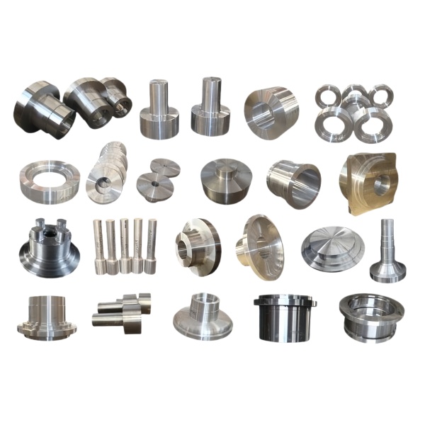
This part belongs to our CNC Machining Parts range. The cnc machining parts pages collect the process notes, common materials and inspection points behind every product in the family.
Specifications
| Item | Stainless Steel CNC Machined Dome Nozzle Housing |
|---|---|
| Brand | AUNOV |
| Designing | Send drawings, or send a housing sample to be measured, a manufacturability review comes back with the quotation. |
| Tooling | Every die designed and built in our toolroom, held and maintained under your part number. |
| Samples | First-off samples of the housing are sent with a dimensional report plus material certs. |
| Materials | 304 / 316 stainless steel is the primary stock for this part, alongside carbon steel (SPCC / DC01), aluminium, brass and copper, and the grade is fixed at the drawing review. |
| Surface finish | Surface treatment per the drawing: plating, e-coat, powder coating, anodising, passivation, fixed at the drawing review. |
| Processing | Staged deep drawing with in-line annealing where needed, then pierced and machined in house. |
| Equipment | 5-250 T mechanical presses plus 250-500 T hydraulic presses, CNC turning and milling cells, a climate-controlled CMM room. |
| Tolerance | Drawn tolerances held to +/-0.1 mm, +/-0.03 mm on machined features. |
| Delivery terms | FOB is standard; DDP offered for EU and US, T/T or L/C, with D/P for repeat business, call-off schedules supported. |
Related Products



Request a Quote for This Part
Send a drawing or sketch — get material advice, tooling cost and a per-piece price within 24 hours (working days).