
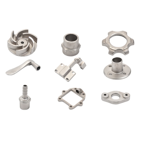
Impeller balance quality is determined by the symmetry of material removal, not by the static balance check alone
A CNC-machined impeller—whether for a centrifugal pump, a blower, or a mixing application—must be balanced to operate without excessive vibration. The balance specification (typically G6.3 or G2.5 per ISO 1940) defines the allowable residual unbalance as a function of operating speed. But the practical question is not whether the impeller can be balanced after machining—it is how much material must be removed during the balancing operation to achieve spec. An impeller that requires 2 grams of material removal from one blade to correct imbalance has inherently asymmetric geometry that indicates a toolpath or fixturing problem; an impeller that requires 0.05 grams is essentially symmetric and the residual is just normal process variation.
We target post-machine unbalance below 0.1 g·mm (roughly equivalent to G2.5 at 3600 rpm for a 1 kg impeller) before the formal balancing operation. This means the impeller should pass a rough static balance check (knife-edge or two-scale balance) with visible settling within 10 seconds. If it does not, we review the CAM program for asymmetrical toolpaths—most commonly caused by machining blades in a single direction (always clockwise around the hub) which introduces a consistent tool-deflection bias that makes each blade slightly different from the last. Alternating the cutting direction (even-numbered blades CW, odd-numbered CCW) cancels this bias and typically reduces the as-machined unbalance by 70–80 %.
Flange flatness and parallelism determine whether the pump casing seals without a gasket
The flange on a machined impeller assembly (or on the mating pump housing) is the sealing surface that must contain the internal pressure. For metal-to-metal sealed joints (common in high-pressure or high-temperature applications where gaskets would degrade), the flange flatness must be better than 0.02 mm TIR over the full gasket area, and the two mating flanges must be parallel within 0.03 mm when the fasteners are tightened to torque.
We machine flanges in the same setup as the bore that locates the impeller shaft, using a facing operation with a fresh insert at 0.1 mm DOC and 200 mm/min feed. After machining, we verify flatness on a surface plate (0.02 mm TIR max) and parallelism between the flange face and the shaft bore axis (0.03 mm TIR per 100 mm diameter). Flanges that exceed the flatness limit receive a grinding pass (reciprocating surface grinder, 0.01 mm stock removal) which reliably achieves 0.005 mm flatness—the gold standard for metal-to-metal seals.
Gear tooth profile accuracy on integral pinions affects noise more than it affects strength
When an impeller assembly includes an integral gear (a pinion shaft that drives the impeller through a gear set), the gear tooth profile quality determines both the transmission error (which generates noise) and the contact stress distribution (which affects fatigue life). In practice, noise is the more sensitive metric: a profile deviation of 0.005 mm (well within most drawing tolerances for AGMA Q9–Q10 gears) can increase the sound pressure level by 3–5 dB at the gear mesh frequency—a difference that is clearly audible and often determines whether the pump passes an OEM acoustic test.
We cut integral gears using a hobbing operation with a precision ground Class AA hob, followed by a shaving pass if the design allows (shaving improves profile accuracy by roughly one AGMA quality grade). For small module gears (m = 0.5–1.0) that are too small for standard hobbing, we use wire EDM to cut the tooth profile directly from solid material, achieving profile tolerance of ±0.003 mm—which is better than most hobbed gears and comparable to ground teeth at a fraction of the cost. The limitation of EDM-cut gears is that the surface has a thin recast layer (5–10 µm) that must be removed by polishing or light honing before service; otherwise, the recast layer spalls off under load and generates debris that damages the mating gear.
Material choice between 17-4 PH, 316, and 2205 depends on corrosion mode, not just “stainless steel” on the drawing
Impellers and gears in pump applications see a range of corrosive environments: freshwater, seawater, chemical process fluids, and oil-water emulsions. Each environment favors a different stainless steel alloy, and choosing the wrong one based solely on cost or machinability leads to premature failure.
- 17-4 PH (UNS S17400): Precipitation-hardening stainless steel with excellent machinability in the H900 condition (hardened to HRC 38–42) and good general corrosion resistance. Ideal for freshwater and mild chemical service where strength-to-weight ratio matters. Not suitable for seawater or chloride-rich environments (pitting corrosion risk). Machinability rating: 70 % of free-machining steel (excellent for a stainless steel).
- 316L (UNS S31603): Austenitic stainless steel with superior pitting and crevice corrosion resistance due to molybdenum addition (2–3 %). The default choice for seawater, food-processing, and pharmaceutical pumps. Softer than 17-4 PH (HRC < 95 HRB in annealed condition) but can be cold-worked for moderate strength. Machinability: 50–60 % of free-machining steel (work-hardens quickly; requires sharp tools and positive rake angles).
- 2205 (UNS S31803): Duplex (austenite-ferrite) stainless steel with roughly twice the yield strength of 316L and superior chloride stress-corrosion cracking resistance. Used for offshore and desalination pumps where 316L would fail by SCC. More expensive and harder to machine (requires slower speeds, more frequent tool changes) but offers the longest service life in aggressive environments.
We default to 316L for all “stainless steel” impeller drawings unless the customer specifies otherwise, because it covers the broadest range of service conditions. We only recommend 17-4 PH when the drawing calls out a specific hardness or strength requirement that 316L cannot meet, and we recommend 2205 only when the customer confirms chloride exposure above 1000 ppm or operating temperatures above 60 °C in seawater.
Bore fit tolerance relative to the shaft determines whether the impeller runs concentrically or orbits
The bore of an impeller (or the bore of the gear hub on an integral gear-shaft) must fit the shaft with the correct interference or clearance depending on the design intent. A press-fit (interference) impeller relies on friction to transmit torque and maintain concentricity; a slip-fit (clearance) impeller uses a key or splines for torque transmission and relies on the fit for centering.
The critical error mode for press-fit impellers is loss of interference due to differential thermal expansion: if the impeller operates at a higher temperature than the shaft (common when the impeller handles hot fluid while the shaft is cooled by bearings), the bore expands more than the shaft diameter and the interference decreases. If the design interference at room temperature is only 0.01 mm (a common minimum for light press-fits), a 50 °C temperature difference between impeller and shaft on a 30 mm bore can reduce the effective interference to near zero—allowing the impeller to shift eccentrically under unbalanced hydraulic forces. We calculate the minimum required interference using the formula δ_min = α·ΔT·D + 0.015 mm (where α is the CTE difference, ΔT is the worst-case temperature delta, D is the bore diameter, and 0.015 mm is a safety margin for assembly variation) and specify this value on our internal process traveler even when the customer drawing shows a smaller number.
How we validate an impeller-gear assembly before it ships as a finished component
When the order calls for a complete assembly (impeller + gear + shaft + bearings, balanced and tested as a unit), we perform a validation sequence that goes beyond individual-part inspection:
- Sub-assembly balance: Balance the impeller on its shaft (with the gear installed) as a rotating assembly. Target: G2.5 at maximum operating speed. Correction by material removal from the impeller shroud (not from the gear teeth or shaft journals).
- Run-in spin test: Mount the assembly in a test housing, drive it to 110 % of rated speed for 30 minutes, and monitor vibration velocity at the bearing housings. Acceptance: below 2.8 mm/s RMS (ISO 10816-3 Zone A) across the full speed range.
- Dimensional interface check: Verify that all mounting dimensions (flange bolt pattern, shaft end thread, keyway size, pilot diameter) match the customer’s interface drawing. Any dimension outside tolerance triggers a review before shipment—even if the part “looks fine” and the customer might not notice until assembly.
- Surface finish and coating verification: Confirm that all specified coatings (anodize, plating, passivation) are present and meet thickness requirements. Check for coating damage at machined edges and threaded holes.
This assembly-level validation adds approximately 45 minutes of labor per unit but has prevented three field failures in the past year where individual parts passed inspection but the assembled unit had an interface mismatch or a balance issue that only appeared when the components were combined.
You will find this part in our CNC Machining Parts range. Process notes, common materials and inspection points for every product in the family are collected across the cnc machining parts pages.
Specifications
| Item | Stainless Steel CNC Machined Impeller Gear and Flanges |
|---|---|
| Brand | AUNOV |
| Designing | Send the drawing, or a sample we can measure, a manufacturability review comes back with the quotation. |
| Tooling | Dies designed and built in our own toolroom, each die held against your part number. |
| Samples | The first-article set ships with a full dimensional report and mill certificate. |
| Materials | 304 / 316 stainless steel leads the stock list for this part, alongside carbon steel (SPCC / DC01), aluminium, brass and copper, with the final grade confirmed at the drawing review. |
| Surface finish | Zinc, nickel or chrome plating, e-coat, powder coat, anodising or passivation, selected against the drawing requirement. |
| Processing | Progressive deep draw stages with in-line annealing as the draw ratio demands, then pierced and CNC-machined in house. |
| Equipment | Press capacity from 5 to 500 T across mechanical and hydraulic lines, CNC turning centres and a climate-controlled CMM room. |
| Tolerance | Drawn tolerances held to +/-0.1 mm, +/-0.03 mm after machining. |
| Delivery terms | FOB as standard, DDP available for EU and US destinations, T/T and L/C; D/P on repeat accounts, call-off scheduling supported. |
Related Products


Request a Quote for This Part
Send a drawing or sketch — get material advice, tooling cost and a per-piece price within 24 hours (working days).