
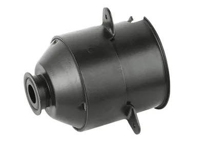
A body that mounts a blower and lives next to a wet coil
The warm wind electric motor body – the structural element that mounts a cabin blower into the HVAC module – has an unusual duty for a steel part: it sits immediately downstream of the evaporator, in a duct that is wet for much of the year. Condensate, dust, and constant moisture cycling make it one of the more corrosion-exposed steel parts in the cabin, while its mechanical job – holding the motor square to the fan and the module – demands stiffness and dimensional stability. This page covers the body’s dual engineering: mounting precision and life in a wet duct.
Mounting the motor to the module
A blower motor mounts into the HVAC module through the body’s mounting features – bolted flanges, locating spigots or snapped interfaces – and its alignment sets the fan’s position within the module’s shroud. Misalignment opens the fan’s tip clearance unevenly, which changes both airflow and noise, so the body’s mounting interface and its bearing seats must share a datum so the fan’s running position is defined by tooling. Our bodies hold the mounting pattern and the bearing seats to the same datum system, verify the fan’s position by a functional gauge where the programme specifies one, and keep the flange flat so the module’s seal or gasket compresses evenly. The body also carries the motor’s vibration into the module, so its mounting features are designed with the module’s materials in mind – formed interfaces with defined contact areas rather than point contacts that concentrate stress in a plastic module.
Life in a condensate zone
Downstream of the evaporator, air is close to saturation and condensate films form on every cool surface. A steel body in that environment corrodes unless its coating is chosen for wet-and-dry cycling rather than for road spray, and the coating must cover the cut edges, the mounting holes and any formed pockets where water collects. We specify finishes rated for cyclic wet service – e-coat or zinc-nickel, generally – and design the body’s geometry so condensate drains rather than pools: no unnecessary flat ledges facing up, drain paths from pockets, and mounting features that do not create a capillary trap against the module. On a part that a driver never sees, this design work is what determines whether the cabin smells of damp metal after five years.
Dust and the body’s internal surfaces
Cabin air is filtered, but not perfectly, and over years a blower body’s internal surfaces accumulate dust that the filter missed. Internal geometry matters for the same reason as on the casing: avoid ledges that collect dust and then shed it into the fan, and keep the body’s surfaces smooth enough that deposits do not build thickly. Where the body has pockets or forming recesses, we check them for dust-trapping geometry at design stage, and where a recess is needed, orient it so its opening faces downward in service. It is a small detail compared with the corrosion and alignment work, but it is the difference between a blower that still runs quietly at year eight and one that develops a rattle when the accumulated dust shifts.
Stiffness and vibration isolation
The body transmits the motor’s vibration to the module, and the module – a large plastic structure with its own resonances – amplifies what it receives. The body’s contribution is to be stiff enough that it does not add compliance (which would let the motor rock) and to present mounting features that let the customer’s isolation strategy work: defined sealing and contact areas for the grommets or isolators the module uses, and a geometry that does not short-circuit them with metal-to-plastic contact. Where a programme has an isolation design, we dimension the body to it rather than around it – which is why we ask for the module’s mounting detail at RFQ, not after the drawing is fixed.
A coating not rated for wet-and-dry cycling
The body drawing with the mounting interface and the module’s mating detail (including any isolators), the fan’s position requirement, the bearing seat or motor mount geometry, the corrosion spec for a wet duct, the thermal duty, and volume. First articles in four to five weeks after die approval, with mounting-pattern metrology, a functional position check if specified, and coating validation included.
Blower bodies corrode inside the duct
Our blower bodies corrode inside the duct – is the coating or the geometry? Usually both: a coating not rated for wet-and-dry cycling, plus pockets that hold water. Send the parts; the corrosion pattern points to the specific pockets, and we can propose a geometry and coating change together.
Can you hold the fan’s alignment through the body alone? Yes, if the mounting features and bearing seats share a datum and the body stays stiff under the module’s clamping. We verify on a functional gauge where the programme specifies one.
Do you supply the body with the motor mounted? On qualifying volumes we can assemble the motor into the body and verify the fan’s alignment, moving a delicate step off the customer’s line. The motor and the fan remain your parts and your specifications.
Choosing between drawing, machining and welding comes down to the shape of the part: the guide to deep drawn covers sets out where each route wins, and the overview page links through to the full Precision Deep Drawn Parts range.
Specifications
| Item | Warm wind electric motor body |
|---|---|
| Brand | AUNOV |
| Designing | Send drawings, or send a sample to be measured – samples are reverse-measured into a controlled drawing; the approved drawing is kept as the controlled master. |
| Tooling | Die design and toolmaking stay in house, so the die charge appears as its own quotation line, and the die remains dedicated to your part. |
| Samples | Sample parts are measured and reported before submission, so the part is proven before it is made in volume, and production starts only after your written sign-off. |
| Materials | Stock runs to carbon steel, 304 / 316 stainless steel, aluminium and brass; the final grade is fixed with the drawing review. |
| Surface finish | Plating, coating or polishing to suit the drawing; finish thickness and adhesion checked on the first article. |
| Processing | Coil blanking and progressive drawing, coining on the final station where the print calls for it; in-process checks sit between stages, not only at the end. |
| Equipment | Press shop running 5-250 T mechanical and 250-500 T hydraulic presses, annealing ovens on site, backed by CNC turning centres and a climate-controlled inspection room. |
| Tolerance | +/-0.05 mm on flange and rim dimensions, wall controlled by the draw; dimensional reports accompany the first article. |
| Delivery terms | Incoterms FOB as standard with DDP on request; sea and air options priced with the order. |
Frequently Asked Questions
Why does this body sit in a worse place than it looks?
Because of where the module puts it. It is mounted immediately downstream of the evaporator, so it lives alternately wet and dry, it sees condensate rather than clean air, and it carries whatever dust came through. None of those are severe alone, and together they decide the coating choice, the drainage and the material in a way a general-purpose enclosure would not need.
How does mounting to the module change the design?
The body is doing two jobs at the mounting interface: holding the motor accurately and isolating its vibration from the ductwork. Those pull in opposite directions, since the stiffest mount transmits the most vibration. Getting both requires thinking about the mount and the body together rather than designing the shell and bolting it on afterwards.
What does life in a condensate zone actually attack?
Repeated wetting and drying, which is harder on coatings than either condition alone. Failure almost always starts where coverage is weakest – edges, laps, around fasteners – rather than on the open panel. It is therefore worth specifying coating performance for cycling rather than relying on a figure measured under steady immersion.
Why do the inside surfaces matter on a part nobody sees?
Because what collects inside eventually becomes what the occupants smell. Moisture that cannot drain and dust that cannot leave turn into odour and microbial growth on internal surfaces, which is a warranty complaint rather than a dimensional one. Providing drainage and reachable internal geometry costs nothing at tooling stage and cannot be added afterwards.
Related Products



Request a Quote for This Part
Send a drawing or sketch — get material advice, tooling cost and a per-piece price within 24 hours (working days).