
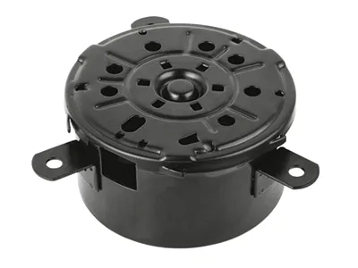
Speed changes everything: the warm wind motor shell at working rpm
A blower motor’s shell sees a regime no other small motor in the vehicle does: continuous operation across a wide speed range, with long periods near its maximum. At those speeds, centrifugal loads on the magnets, dynamic balance of the rotating assembly, and the shell’s own response to vibration become the engineering focus. A warm wind motor shell is therefore designed around speed rather than torque – the opposite emphasis to a window or wiper motor – and this page covers what running fast demands of the shell.
Magnet retention at sustained speed
A bonded magnet inside a spinning shell is loaded by two things: the shell’s own expansion and the loads transmitted through the bond. At a blower’s continuous maximum speed, those loads persist for hours rather than seconds, which is a different test of the joint than a window motor’s brief pulses. The shell’s contribution to magnet survival is roundness and uniformity of the magnet land – a uniform bond line shares the load evenly, a variable one concentrates stress at its thin points – and a land whose surface is prepared for bonding (specified roughness, verified cleanliness, dyne level checked) so the adhesive’s strength is realised rather than assumed. We hold the magnet land’s roundness to a tight band, verify wall thickness by mapping, and supply bond-readiness certificates for shells destined for bonded-magnet assemblies, exactly as on our other magnetic shells.
Balance and runout
At several thousand rpm, a rotating assembly’s balance is dominated by the armature and fan, but the shell matters through the alignment it gives them. If the shell’s bearing seats are off-centre or its bore not straight, the armature runs eccentric, and an eccentric rotor at speed produces vibration and noise that no balancing operation can fully remove. Our shells hold bearing-seat concentricity and straightness by the same sizing and coining discipline used across the motor family, and the shell’s own dimensional consistency is verified on first articles against the customer’s alignment gauges. This is the shell’s quiet contribution to a quiet blower – a contribution that shows up as a population with consistent vibration rather than a scattered one.
Shell stiffness and the shaft’s dynamic behaviour
A blower’s shaft, fan and rotor form a dynamic system whose critical speeds depend on the supports – the bearing seats – and on the shell’s stiffness between them. A shell that flexes under load changes the system’s stiffness and therefore its critical speeds, potentially bringing one into the operating range. Formed shells address this with structure rather than mass: a flange or a formed stiffening feature between the bearing seats, a wall thickness chosen to place the shell’s own modes away from the shaft’s operating range, and, where the design allows, a geometry that shortens the unsupported span of the shaft. On programmes where the fan’s speed range is wide, we recommend a check of the assembled system’s critical speeds against the operating range as part of first-article validation, because it is cheaper to find a resonance on the bench than in a vehicle.
Thermal duty over hours
The shell’s thermal role differs from other motors because a blower’s duty is continuous: heat accumulates in the bearing seats and the shell until the system reaches equilibrium, and that equilibrium is what the materials see for hours. A shell whose bearing seats were validated at a brief peak temperature may still lose their press-fit band at the sustained equilibrium temperature, so blower shells are validated at the customer’s continuous operating temperature rather than at a transient peak. We also consider the shell’s thermal expansion relative to the magnets: a shell that grows more than the magnet land’s bond can accommodate will eventually fail the bond, and the differential is a design variable, not an accident.
Balance first, then the bearing seats
The shell drawing with diameter, depth, wall and material; the magnet architecture (bonded or pole-mounted) and bonding spec; the bearing seat requirements and the shaft’s alignment tolerance; the continuous and peak operating temperatures; the speed range; the corrosion spec; and volume. First articles in three to four weeks after die approval, with wall mapping, magnet-land roundness and bond-readiness records included as standard for bonded-magnet programmes.
Blowers vibrate at certain settings
Our blowers vibrate at certain settings – is the shell or the balance? Usually balance, but a shell whose bearing seats are off-centre shifts the vibration into the population, so we measure both. Send assembled blowers and shells; the metrology and the vibration data together identify which is dominant.
Can you hold magnet-land roundness for a high-speed blower? Yes – the same tight band we hold for our yoke and can programmes, verified by a first-article map. If your speed requires tighter than we can hold as drawn, we will say so and quote a finishing pass.
Do you supply shells with magnets bonded? On qualifying volumes, yes – bonded, cure-verified and pull-tested to your specification. The magnet and adhesive stay yours; the process and its verification become ours.
The design decisions behind a part like this — draw ratio, wall thinning, radii and trim — are worked through with numbers in our deep drawn covers guide, and the Precision Deep Drawn Parts pages collect the rest of the family.
Specifications
| Item | Warm wind motor shell |
|---|---|
| Brand | AUNOV |
| Designing | Driven by your drawing or a physical sample – a manufacturability review comes back with the quotation; the approved drawing is kept as the controlled master. |
| Tooling | Progressive and drawing dies are designed and built in house, so the die charge appears as its own quotation line, and the charge is refundable against agreed volumes. |
| Samples | Sample lead time is quoted with the order, and the approved sample governs the run. |
| Materials | Carbon steel (SPCC / DC01), 304 / 316 stainless steel, aluminium, brass and copper – the grade is matched to the duty of this shell. |
| Surface finish | The print decides between natural, plated or coated; we log the agreed finish and check thickness and adhesion on the first article. |
| Processing | Deep drawing from coil or blank, with in-process annealing so walls thin evenly; batch records are filed so a repeat order starts from approved data. |
| Equipment | 5-250 T mechanical presses, 250-500 T hydraulic presses and annealing furnaces in line; secondary ops run on CNC turning centres, inspection on the CMM. |
| Tolerance | +/-0.05 mm on formed features, with capability data on critical dimensions; critical dimensions carry CMM data with the shipment. |
| Delivery terms | FOB, CIF or DDP per Incoterms – payment by T/T or L/C, with shipping quoted door-to-door. |
Frequently Asked Questions
Why does this shell see a regime no other small motor in the vehicle does?
Because of how it is used rather than how it is built. It runs continuously across a wide speed range and spends long periods near the top of it, which is unlike motors that cycle briefly. That combination puts sustained load into features that a part designed for intermittent duty would consider lightly stressed.
What holds the magnets at sustained speed?
The shell’s grip, and that grip depends on geometry that changes with temperature. Centrifugal load and differential thermal expansion both act to loosen what was assembled cold, so if the shell has relaxed or ovaled there is nothing left to hold against. Retention is therefore a shell property as much as an adhesive one.
Why is balance addressed before the bearing seats are finished?
Because the correction has to survive everything done afterwards. Balancing first removes material where it is useful; finishing the seats afterwards then guarantees those machined surfaces stay true to the corrected axis. Doing it the other way round risks the final machining undoing the very relationship the balancing established.
What does thermal duty over hours do to the shell?
It lets things settle. Material relaxes slightly under sustained heat, interference fits change, and anything assembled pre-loaded can end up less loaded than it started. That is why acceptance is better judged after the part has been through its thermal history than when cold on the bench, where nearly everything measures better than it will later.
Related Products


Request a Quote for This Part
Send a drawing or sketch — get material advice, tooling cost and a per-piece price within 24 hours (working days).