
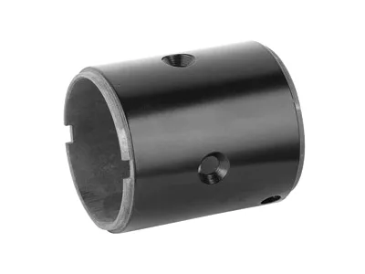
What “deep drawn can” means in manufacturing terms
A deep drawn can is a closed-bottom cylindrical shell drawn from flat sheet in one continuous forming sequence – the metal does not start as tube and it has no welded side seam. The word “can” covers everything from a 8 mm oxygen sensor shell to a 150 mm filter body, and the reason engineers specify a drawn can instead of a fabricated one is always the same set of properties: seam-free wall, controlled wall thickness, and a base that is integral to the body rather than joined to it.
Where a welded-and-capped fabrication has three failure points (two seam welds and a roll joint), a drawn can has none. That is why battery cans, sensor housings, aerosol bodies and filter shells – products whose failure is expensive or dangerous – are drawn, not assembled.
Size and proportion: what the draw ratio allows
The practical envelope on our presses:
- Diameters 6-160 mm for round cans; square and rectangular cans to 200 mm across the diagonal with proper corner radii.
- Depth up to 2.5:1 depth-to-diameter as-drawn in steel and aluminium; 3:1 and beyond for stainless steel with intermediate annealing. A classic example: a Ø25 mm can drawn 70 mm deep in DC01 steel on a four-station transfer die.
- Wall 0.4-3.0 mm depending on diameter; ironing can thin walls 10-25% per pass and bring the wall variation under 4% of nominal.
- Volumes internal, so to speak: cans run from 2,000 pieces a year (soft-tooled industrial parts) to 300,000 a month (automotive sensor shells on hard transfer tooling).
If a drawing asks for more depth than the material allows in one hit, the answer is not “no” – it is a redraw schedule. The quotation shows the sequence so you can see exactly what the depth costs.
The forming sequence behind a typical can
Every drawn can follows the same logic; the variables are how many stations and where annealing sits:
Blank calculation. Blank diameter comes from surface-area unfolding plus 3-8% trim. Getting this right matters more than most buyers expect – an undersized blank starves the wall on the first draw and the can tears at station three, which is a tooling iteration you pay for. We run the unfolding in simulation before cutting steel.
First draw (cupping). Forms a cup about 50% of the final depth. The die radius and blank-holder pressure are set per material: soft aluminium needs generous radii and low pressure; stainless steel needs higher pressure and chlorinated lubricant to stop galling.
Redraws. Each pass reduces diameter 15-20%. Between deep passes, cans are bright-annealed in a protective atmosphere – no scale, no pickling, no hidden surface damage.
Base forming. Domes, dishes orpierced holes are formed in the final stations. A domed base adds pressure resistance; a flat base with a coined gasket face seals against a mating lid.
Trimming and finishing. Open ends trimmed in-die for ±0.5 mm, or machined for ±0.1 mm where a seal or thread follows.
Material choice by duty
- DC01 / SPCC carbon steel – the volume default. Painted, plated or e-coated after drawing; used for motor cans, solenoid shells, filter bodies.
- 304 / 316 stainless steel – corrosion duty and anything that stays bare: sensor shells, medical containers, food-contact parts. 316L for chlorides; passivation to ASTM A967 on request.
- Aluminium 1050 / 3003 / 8011 – lightweight and thermally conductive cans: capacitor cans, battery cells, heat-spreading housings. Anodising or chemical conversion after draw.
- Copper, brass, phosphor bronze – conductive and RF cans; EMI shielding cans drawn in one piece keep a continuous conductive path a folded-and-welded can cannot match.
Material certificates EN 10204 3.1 accompany every batch, with heat numbers traceable from coil to shipping carton.
Tolerances you can hold us to
- OD as-drawn ±0.10 mm; after ironing/sizing ±0.05 mm.
- ID ±0.05 mm on ironed cans (the punch sets it).
- Depth ±0.5 mm in-die trimmed; ±0.2 mm with trim station.
- Wall eccentricity 5-8% of wall as-drawn; under 4% ironed.
- Base dome height ±0.3 mm; flange flatness 0.3 mm per 100 mm as-formed, 0.1 mm coined.
Machined features after drawing (faced rims, threaded bosses, seal grooves) hold ±0.03 mm on our CNC centres in the same plant.
Verification matched to function
A can that holds pressure gets leak-tested – pressure-decay or vacuum, 100% or AQL per your spec. A can that carries a bearing gets roundness traces and SPC on the fit diameter. A medical or food can gets surface-finish Ra readings and material PMI. First articles ship with a full layout report against your drawing; running batches carry the SPC charts on the key characteristics we agree at launch. Nothing in this chain is outsourced – forming, machining, measurement and testing share one roof and one quality system.
Where drawn cans are working today
- Oxygen sensor and lambda sensor shells in stainless steel, drawn deep with pierced base ports, tens of thousands per month.
- Battery and supercapacitor cans in nickel-plated steel and aluminium, wall ironed for capacity.
- Solenoid and motor cans in DC01, e-coated, with coined bearing seats.
- Aerosol and dispenser bodies with domed pressure bases.
- EMI shielding cans in brass and phosphor bronze for telecom boards.
Questions we are asked about drawn cans
Can you make the can and the lid as a matched pair?
Yes – drawing both from one controlled drawing set means the flange diameters and gasket lines are dimensioned against each other, not negotiated between two suppliers after the fact.
What is the smallest can you can draw?
Diameters down to about 6 mm are routine. Below that, the punch-to-clearance ratios get specialist; send the drawing and we will tell you honestly whether drawing or machining wins at your volume.
Do you carry tooling for standard can sizes?
We keep a small library of existing can tools for common diameter/depth combinations. If one fits your part with minor changes, first articles come in days instead of weeks and tooling cost drops sharply – always worth asking before commissioning new dies.
What to send, and what we need to know first
Send the drawing (STEP/PDF) or a sample, the annual volume, and the working environment – pressure, temperature, media. The quotation shows the die sequence and station count, so the price structure is visible and design trade-offs can be evaluated with numbers, not guesswork.
Not sure whether to draw, machine or weld this geometry? The guide to deep drawn covers compares the three routes and shows where each one wins; the full Precision Deep Drawn Parts range is linked from the overview page.
Specifications
| Item | Deep drawn can |
|---|---|
| Brand | AUNOV |
| Designing | Quotation follows the print, not a catalogue – unusual walls, threads or tolerances are feasibility-checked first; changes are priced before they are made. |
| Tooling | Dies, fixtures and gauges are made in our own toolroom, so die cost stays transparent, and the charge is refundable against agreed volumes. |
| Samples | Samples are produced on the production tooling, so what you approve is what you get. |
| Materials | Stock covers carbon steel (SPCC / DC01), 304 / 316 stainless steel, aluminium and brass; the final grade is fixed with the drawing review. |
| Surface finish | Finish selected from the drawing: plating, coating, anodising or passivation; the agreed finish travels with the part number. |
| Processing | Deep drawing on maintained presses, blank size and lubrication logged per run; batch records are filed so a repeat order starts from approved data. |
| Equipment | Mechanical presses from 5 to 250 T and hydraulic presses 250-500 T, with in-line annealing furnaces; secondary ops run on CNC turning centres, inspection on the CMM. |
| Tolerance | +/-0.05 mm on formed features, with capability data on critical dimensions; dimensional reports accompany the first article. |
| Delivery terms | Standard terms FOB; DDP available for EU and US, with T/T and L/C accepted. |
Related Products
Request a Quote for This Part
Send a drawing or sketch — get material advice, tooling cost and a per-piece price within 24 hours (working days).