
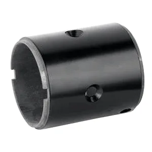
The starter body: carrying the shift lever and the solenoid
A starter’s mechanical drama happens at its drive end – the pinion must shift into mesh with the flywheel, crank, and retract – and the auto starter motor body is what mounts and reacts that whole mechanism. It carries the shift lever’s pivot, the solenoid’s mounting, and the loads the pinion engagement generates, all in an environment of cranking shocks and engine-bay heat. This page covers the body’s mechanical integration: the features that make the pinion mechanism work, and the forming choices that keep them accurate.
The solenoid mount and the shift lever pivot
On most starter architectures, a solenoid mounted on the body pulls a shift lever that pushes the pinion into mesh. That gives the body two precise features: the solenoid’s mounting face and bolt pattern, and the shift lever’s pivot. Both must be positioned so the lever’s geometry produces the correct pinion travel – a fraction of a millimetre of pivot misplacement changes the engagement depth, and a pinion that engages too shallowly strips flywheel teeth. Our body designs place these features by in-strip forming and piercing, tied to the same datum as the pinion bore and the mounting flange, so the mechanism’s geometry is set by tooling. We validate engagement with a functional gauge that mimics the flywheel’s ring gear position before any parts ship.
Reaction loads from the drive mechanism
The pinion’s engagement and the cranking torque both generate reactions the body must carry. Engagement produces a largely axial thrust as the pinion is pushed into mesh against the return spring and any tooth-to-tooth interference; cranking produces a torque reaction taken partly by the body’s mounting to the engine and partly by its internal load paths to the pinion bore. We size the body’s walls and formed features for these combined loads, keeping the path from the pinion bore to the mounting flange short, and radius the local features generously where load concentrates. Starter bodies that fail in service typically show cracks or distortion radiating from a sharp local form – a specific, avoidable geometry problem.
Forming the body accurately at starter scale
Body shells for starters are typically large-diameter, medium-depth draws with several formed features – the solenoid mount, the lever pivot, a drive-end register, often a formed boss for an electrical connection. Achieving them in one progressive or transfer die requires larger tooling than accessory parts, and the die’s accuracy class is correspondingly higher. Our starter body tooling uses the same insert-based approach as our other motor parts, so features can be tuned or revised at insert level rather than rebuilding the die – important on starter programmes, whose mechanisms often evolve during development. Wall thickness across the body is mapped on first articles because, as on every starter shell, thickness uniformity serves both the mechanical load paths and the magnetic return.
Coating, corrosion and the drive end
Starter bodies face under-hood corrosion with one added complication: the drive end is exposed to the flywheel housing’s environment, where clutch dust, oil mist and spray collect. Coating the body for cyclic under-hood conditions is the baseline, but the drive-end faces and any mechanism interfaces often need to be kept free of heavy coating for fit and function. We coordinate that masking with the plating or coating line so the functional faces stay to their required specification while the rest of the body gets full protection. This dual-specification approach is standard on starter parts and should be explicit on the drawing.
Engagement depth is set by the lever geometry
The body drawing with the solenoid mount, lever pivot, drive-end register and pinion bore; the starter’s mechanism geometry (pinion travel, engagement depth); the cranking torque and engagement thrust loads if known; the under-hood corrosion spec; and volume. First articles in four to five weeks after die approval, with engagement verification included for programmes that specify it.
Starters strip flywheel teeth – is the body at fault?
Our starters strip flywheel teeth – is the body’s geometry at fault?
Engagement depth is set by the lever geometry the body locates, so a worn pivot or a shifted mount is a plausible cause. Send the body and the starter’s engagement data; our gauge check usually isolates whether the body moved or the mechanism wore.
Can you form the solenoid mount integrally?
Yes – it is die geometry, positioned to the same datum as the pivot and pinion bore. Integral mounting also avoids the distortion and corrosion risk of a welded bracket.
Do you supply the body with the lever mechanism fitted?
On qualifying volumes we can install and gauge the shift mechanism to your print, moving a delicate assembly step to us where it can be verified. The mechanism’s parts and specification remain yours.
This part belongs to our Automotive Motor Components range. The automotive motor components pages collect the process notes, common materials and inspection points behind every product in the family.
Specifications
| Item | Auto starter motor body |
|---|---|
| Brand | AUNOV |
| Designing | Send drawings, or send a sample to be measured – unusual walls, threads or tolerances are feasibility-checked first; the agreed version governs every later batch. |
| Tooling | Tooling is built and held under your part number, so no tooling step is outsourced, and maintenance is tracked against the part number. |
| Samples | Samples are issued for approval before the run, so any deviation is corrected at sample stage, and production starts only after your written sign-off. |
| Materials | Stock list: carbon steel, 304 / 316 stainless steel, aluminium, brass; the final grade is fixed at the drawing review. |
| Surface finish | Zinc or nickel plating guards against corrosion; housings can take powder coating or electrophoresis, and laser etching is available on request. |
| Processing | Deep drawing runs from coil or blank; in-process annealing keeps wall thinning even, and trim, pierce, form and finish follow. |
| Equipment | 5-250 T mechanical and 250-500 T hydraulic press lines, in-line annealing furnace, with CNC turning covering secondary work. |
| Tolerance | +/-0.05 mm to +/-0.1 mm across the part; tighter bands confirmed against the die before the quotation is fixed. |
| Delivery terms | FOB Ningbo or Shanghai, payment by T/T or L/C, quoted in USD or EUR; call-off schedules are supported. |
Related Products


Request a Quote for This Part
Send a drawing or sketch — get material advice, tooling cost and a per-piece price within 24 hours (working days).