
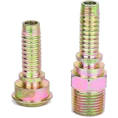
A nozzle tip is small, it is on the end of a fuel line, and it decides how the fuel leaves. Which means its two most important features are a hole and the shape of that hole, and both of them are usually drawn as a diameter with a tolerance and nothing else – which is the least useful way to draw either of them.
Chrome plating on this part comes third in importance and it is worth understanding why it is specified. It is not corrosion protection. It is wear resistance at the orifice, and it is also a bearing surface for whatever the nozzle seats against. Once that is clear, the plating specification and the dimensional scheme both follow rather logically.
What the orifice actually decides
A nozzle tip’s orifice sets three things that a customer cares about, and they are not the same thing:
- Flow rate, which at a given pressure differential is set by the orifice area – and area varies with the square of the diameter. A 5 percent error in diameter is roughly 10 percent in area and roughly 10 percent in flow. On a calibrated fuel or fluid delivery, this is the dimension that matters, and it is therefore the dimension that cannot be left to the general tolerance.
- Spray pattern and penetration. This is set by the internal geometry upstream of the orifice – the chamber volume, the approach angles, the length-to-diameter ratio of the orifice itself – not by the orifice alone. Two nozzles with identical orifice diameters will spray differently if their internal contours differ, which is why spray pattern is a specification that cannot be reduced to a drawing dimension.
- Exit velocity and atomisation. A longer, narrower orifice produces a higher velocity jet at a given flow, which improves atomisation. This is why orifice length is a real dimension on a fuel nozzle and not an accident of the manufacturing process.
So on this part the orifice needs three specified properties rather than one: the diameter to a tight band, the length, and the form – the roundness and the wall condition at the exit. And the spray pattern needs to be established by a functional reference rather than by geometry alone, which is a different kind of specification entirely.
The orifice, and the three ways it gets made
The method used to make the hole determines what can be held, so it belongs on the drawing as a decision rather than as an assumption.
Drilled
A twist drill at small diameter. Fast, economical, and the standard for larger orifices.
- Roundness on a small drilled hole is typically not excellent, and it is worse in stainless steel and in hard materials.
- Position comes from the drill’s wander, which on a small hole is a real fraction of the diameter.
- The exit end carries a drill burr and a drill point geometry, and on a nozzle that is a functional surface.
- Breakout burr on the exit side must be removed deliberately, and its removal is a second operation that can change the edge of the orifice.
Reamed
A drill followed by a reamer. Better roundness, better size control, better finish – and this is the usual answer when the orifice is a calibrated flow feature.
- The cost is an extra operation and a tooling consumable, and on a very small orifice the reamer can be the limiting factor on capacity.
- Reaming cannot recover a badly placed hole. The reamer follows the drill, so a positional error survives the reaming. Position has to come from a located setup or a secondary operation.
Ground or lapped
For a small calibrated orifice, a form tool or a fine grinding operation gives the best roundness, the best size control, and the best surface. This is what a precision fuel nozzle orifice will be.
- Surface finish matters on an orifice. A rough internal surface in the orifice raises the pressure drop and can promote cavitation at the exit, and it changes the spray.
- The cost is significant and the capacity is limited. This is the right answer on a calibrated part and the wrong answer on a general one.
The honest way to write this on a drawing is to state the required tolerance on the orifice diameter and let the process meet it, because specifying the process removes the shop’s ability to choose a cheaper route that still achieves the tolerance. Specifying the orifice’s tolerance, roundness and length achieves the same control without foreclosing the method.
Chrome plating, which is a wear decision
Hard chrome here is doing wear resistance at the orifice and, on a seating nozzle, providing a hardened bearing face against a valve seat. Two consequences follow, and one of them is frequently missed.
The orifice and plating
Plating builds material onto every surface, including the inside of the orifice. That has two effects, pulling in opposite directions:
- The orifice gets smaller. Chrome deposits inside a small bore, and the reduction is roughly twice the nominal thickness. On a 1 mm orifice plated to 0.02 mm, the bore closes by about 0.04 mm – four percent of diameter, and therefore about eight percent of the flow area. This is not a defect; it is a predictable consequence, and it is entirely manageable provided everyone knows about it.
- Surface finish improves, because plating fills the drill marks and reaming marks. An orifice that is reamed and then plated often has a better internal surface than one that was reamed alone.
So the specification practice that matters here is short and specific: state whether the orifice diameter is before or after plating, and give the plating thickness range. Without it, the orifice that arrives is smaller than the drawing says, the flow is lower than expected, and the cause is invisible. This is the single most useful sentence on a plated nozzle’s drawing.
The plating is brittle, and where it is stressed
Hard chrome is hard and it is brittle relative to the steel beneath it. On a nozzle tip the interesting stress case is not the orifice – which is in compression from the pressure – but the outside of the tip, where the pressure also acts, and any feature where the plating has to follow a change of direction.
Two practical items: the plating should be kept off any thread that will be screwed in, because plating on a thread changes the fit and the chrome will flake at the thread’s roots; and any sharp corner on the part is a place where the plating will crack, so the corner radii need to be generous enough to survive the deposition process rather than sharp enough to look crisp.
The tip as a valve, when it is one
On a nozzle tip that seats against a valve or a poppet to shut flow, the tip’s face becomes a sealing face and a wear face simultaneously, and the requirements change substantially.
- Flatness and perpendicularity of the seating face become functional, because that face is what closes against another surface. A face that is not square to the axis will not seal evenly, and a chamfer on a seating face is not decorative – a chamfer is a sealing land, or it is a leak path, depending on which face it is on.
- The contact pattern between the tip and its seat is worth establishing at first article, because a nozzle that contacts on one edge will wear into an ellipse and then leak. Plating helps here: a hard chrome face against a hardened seat gives a much longer life than bare steel on bare steel.
- Hardness pairing. Chrome against a hardened seat is the right pairing. Chrome against a soft brass or aluminium seat will cut it, and the wear debris will end up in the orifice.
A nozzle tip is chosen by fluid and temperature, not by machining
Carbon steel, 304 and 316 stainless steel, aluminium and brass are all held for this route, and for a nozzle tip the choice is usually made by the fluid and the temperature rather than by machining.
- Carbon steel plated in hard chrome is the classic fuel and hydraulic nozzle material, and it is a good one: cheap, hardenable, and the chrome carries the wear.
- Stainless Steel where the fluid is corrosive or where higher temperature rules out a plated steel tip. It machines less well and the orifice is harder to hold, but it will not corrode.
- Brass on fluid and air applications where galling against a brass or aluminium seat is a concern and where no flame or high temperature is involved. Brass machines well, which helps on a small part with a small orifice.
- Aluminium is essentially never right for a nozzle tip that sees pressure and wear – it has poor wear resistance and poor thread and seating durability, and its thermal expansion moves the orifice.
A general band is adequate here, except at the orifice
+/-0.01 mm on turned and milled features is achievable, and on this part that general band is entirely adequate for everything except the orifice. So the specification effort should go into the orifice and the seat, and the general tolerance should be left general.
- Orifice diameter, measured, on every part, with the measurement method stated – an air gauge, a flow test, or a gauge pin – because a value measured differently means nothing.
- Orifice roundness, and specifically the roundness at the exit end where a drilled hole is least round.
- Orifice length from the exit face to the chamber.
- Exit edge condition – no burr, no break that would change the effective diameter. This is where the plating will also gather if there is a burr beneath it.
- Flow verification at a stated differential pressure, if the application calls for a calibrated delivery. This is the only test that tests the specification the customer actually cares about, and on a calibrated fuel nozzle it is the appropriate acceptance test.
- Plating thickness and adhesion, on the first article, with the orifice’s plating condition explicitly stated and any masked areas verified.
- Seating face flatness and, on a seating tip, a contact pattern check against a master seat on the first article.
A calibrated orifice, or one that only has to deliver
Is this orifice calibrated – does the flow rate matter, or does the tip only need to deliver fluid? A calibrated orifice needs a diameter held to a tight band, roundness held, and very likely a flow test on every part; it also needs the plating thickness and the pre-plate bore size coordinated, because a calibrated dimension cannot be allowed to move by eight percent of the flow area between operators. An uncalibrated tip needs a general tolerance on the orifice and a lot of attention on the exit edge condition and on corrosion resistance. The two parts are similar in size, similar in material and entirely different in how they are made and inspected, and the question that separates them costs nothing to ask. It is worth asking it, and worth stating on the drawing which side of the line the part is on.
You will find this part in our CNC Machining Parts range. Process notes, common materials and inspection points for every product in the family are collected across the cnc machining parts pages.
Specifications
| Item | Chrome-Plated Multi-Barb Hose Nozzles, Two-Piece |
|---|---|
| Brand | AUNOV |
| Designing | Driven by your drawing or a physical sample – unusual walls, threads or tolerances are feasibility-checked first; the approved drawing is kept as the controlled master. |
| Tooling | Dies, fixtures and gauges are made in our own toolroom, so die cost stays transparent, and maintenance is tracked against the part number. |
| Samples | Prototype and pre-production samples are provided against the drawing, so any deviation is corrected at sample stage, and the signed sample is kept for future reorders. |
| Materials | Stock covers carbon steel (SPCC / DC01), 304 / 316 stainless steel, aluminium and brass; material substitutes are proposed only with your written approval. |
| Surface finish | Plating, powder coating, anodising or polishing, per the print; the agreed finish travels with the part number. |
| Processing | CNC turning with milling and drilling in as few setups as the geometry allows; in-process checks sit between stages, not only at the end. |
| Equipment | CNC turning centres with bar feeders and 3-/4-axis machining centres, with CNC turning centres for secondary operations and CMM inspection. |
| Tolerance | +/-0.01 mm on turned and milled features; critical dimensions carry CMM data with the shipment. |
| Delivery terms | FOB Ningbo or Shanghai, T/T with deposit and L/C for larger runs; repeat orders reuse the approved first article. |
Related Products


Request a Quote for This Part
Send a drawing or sketch — get material advice, tooling cost and a per-piece price within 24 hours (working days).