
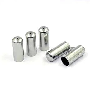
A small pipe part is a fluid boundary with a manufacturing tolerance problem attached
A small deep drawn pipe part – a tube, a sleeve, a stub, a fitting body – carries fluid. That is the whole of its function, and it means the part is a pressure boundary, a corrosion boundary, and a dimensional fit, all at once, on a component that is often small enough that the process effects are as large as the design features. This is a part type where the interesting engineering is almost never in the shape. It is in the wall’s variation, the bore’s quality, and the surface where the fluid actually sits.
We deep draw on maintained presses with blank size and lubrication logged per run, and batch records are filed so a repeat order starts from approved data, on mechanical presses 5-250 T and hydraulic presses 250-500 T with in-line annealing furnaces, with in-house toolmaking keeping dies and fixtures maintained. Drawn diameters to +/-0.05 mm with tighter bands confirmed against the drawing, and dimensional reports accompany the first article. Materials held include carbon steel, 304 and 316 stainless steel, aluminium and brass, with special grades sourced to the drawing when volumes justify. Finish is selected from the drawing – plating, coating, anodising or passivation – with alternatives quoted with the quotation and samples approved in writing. This page is about what carrying fluid demands, and the four places a small drawn part fails to meet it.
The wall is a pressure calculation and a material specification at once
On a small pipe part the wall has to do three things, and the drawing has to address all three:
- Carry the pressure. For a thin-walled cylinder the hoop stress governs, and the required wall follows from the pressure, the diameter, and the material’s allowable stress. On a small diameter the required wall is genuinely thin – often well under a millimetre – which is what makes a drawn part possible at all.
- Survive the drawing process. A wall that is theoretically adequate for the pressure may still tear during the draw, because the draw stretches the wall and the thinning concentrates at the punch nose. So the process imposes a minimum that is often above the pressure requirement – and the drawing’s wall has to satisfy the process, not just the pressure.
- Not be consumed by corrosion. Where the medium is corrosive, a corrosion allowance has to be added on top of the pressure requirement. This is standard on pressure work and it is routinely missing on a small drawn part where nobody thinks of the part as pressure equipment.
And the honest constraint: the wall on a drawn part is inherited from the incoming material. The press modifies it but does not set it, so a wall specification on a drawn pipe part is fundamentally a purchasing specification. Where a tight wall band is needed – because the pressure calculation has no margin – the material has to be bought to a thickness specification, and that is a cost and a lead-time decision that belongs at quotation rather than in a review after the first batch.
The bore, and why a drawn bore is rarely what a fluid part needs
A pipe part’s bore is a flow passage and it is where most of these parts’ problems live. Four specific deficiencies of a drawn bore, and they compound on a small part:
- Taper. The wall thins during the draw, so the bore’s diameter changes along its depth. On a small part the absolute change is small but the relative change is not, and a tapered bore gives an uneven flow and an uneven seal.
- Surface. A drawn bore carries draw marks and is work-hardened at the surface. On a wetted bore that is a surface condition a gasket or a seal has to deal with, and on a bore that carries a fluid it is a place for deposits to start.
- Roundness. A drawn bore’s roundness follows the punch, and on a small part where the tolerance band is a large fraction of the diameter, an oval bore is a measurable defect.
- Burr and cleanliness. A drawn or pierced end carries a burr, and on a small bore a burr is a significant obstruction to flow and a site for accumulation. This is a real problem in fluid-handling parts and it is a specified requirement rather than a finishing nicety.
Where any of these matters, the bore is machined – reamed, honed, or bored and finished – and this is why the tight band on a small pipe part belongs to machined features rather than to drawn ones. The general drawn band of +/-0.05 mm on diameters is a tooling and material specification; the bore that has to hold a seal or a flow is a machining specification.
Ends, seats and the four things a pipe part connects to
A small pipe part has at least two ends and each is a connection, and the four connection types have different requirements:
| Threaded end | Requires enough thread engagement to carry pressure without stripping, which in a drawn small part means a wall or a boss. A thread cut into a drawn small-diameter part is a genuine engineering check, not a routine feature. The thread’s sealing method – bonded seal, tapered thread, or an O-ring – changes the part’s end geometry entirely. |
|---|---|
| Flared or cone seat | A machined cone that a mating tube or fitting seals against. This is a tight-band, tight-tolerance feature with a defined angle and surface, and it is the normal answer where a small pipe part connects to a tube. It cannot be a drawn feature. |
| Face seal | A flat face with an O-ring or a bonded seal. The tightest option and the most sensitive to flatness and finish, and it usually requires a machined face. On a small part the face’s flatness and the bore’s perpendicularity to it are the two things that make the seal work. |
| Insert or press-fit end | Where the pipe part is pressed into a mating part. Then the interference is a specified value, the OD is the controlling dimension rather than the ID, and the part’s concentricity matters because it determines how evenly it presses. |
In every case the requirement is a property of the pair – the part and whatever it connects to – and the drawing should say what the mating part is, or at minimum its critical dimensions. A pipe part specified without knowing its mating part is specified without knowing what it has to do.
Corrosion, and the alloy-medium pairing
Materials held include carbon steel, 304 and 316 stainless steel, aluminium and brass, with special grades sourced to the drawing when volumes justify. On a fluid-carrying part, the alloy and the medium have to be paired deliberately:
- 304 stainless steel for water, air, and many mild chemicals. The default for a fluid part where nothing specific is required.
- 316 stainless steel where chlorides, salt water, or acidic content are present – which covers a great deal of process equipment, and where 304 is a common and expensive mistake.
- Carbon steel for a non-corrosive medium where cost governs, and it needs a coating – but a coating on the inside of a small bore is a coverage problem, so an internally coated small part is worth discussing rather than assuming.
- Aluminium where mass matters, and it is a good choice for many fluid media – but aluminium’s oxide is a poor barrier to some media, it can leach ions, and it corrodes in alkaline cleaning chemistries. On a fluid part the medium has to be named.
- Brass for water, and for many oils and fuels. It is the classic plumbing and instrumentation material and it is stable in a wide range of ordinary media. Its limit is dezincification in acidic or ammonia-bearing conditions.
And on the finish, which on a fluid part is usually a corrosion requirement rather than an appearance one: plating a small bore is a coverage problem, passivating stainless steel is dimensionally neutral and gives full corrosion resistance, and a coating inside a bore that will hold a stagnant fluid is a coating that will eventually fail at its thinnest point – which is the inside of the bore.
A sleeve or a fluid path are different parts
Eight things, and the first three are what turn a small drawn shape into a fluid component:
- The medium, its temperature, and its pressure – or whether it is a low-pressure fluid and the wall is set by handling rather than by pressure. Without this, the wall and the material are guesses.
- Wall thickness, with its tolerance and its minimum location, and an acknowledgement that this is a material specification. Where a tight band is needed, the incoming material specification that achieves it.
- What each end connects to, or at minimum the mating part’s thread, seat, or face specification – because the connection is a property of the pair.
- Where the bore is functional, whether it is machined or as-drawn, with its tolerance and roundness as separate requirements.
- Any seal’s specification, and which surfaces are masked from the finish so the seal’s geometry is what the drawing says.
- Whether the bore’s surface finish is a requirement, and the burr limit at any cut end.
- Material grade, and the reason for it, confirmed in writing – tied to the specific medium.
- Critical dimensions with CMM data, and the tighter bands confirmed against the drawing before quoting.
Is this part fluid-carrying at all?
Is this part fluid-carrying at all, or is it a sleeve around something else? A small drawn tube is very often a protective sleeve, a spacer, or a conduit for a cable or a hose, and on those parts the wall is a handling and stiffness requirement rather than a pressure one – which is a very different specification and a much cheaper one to meet. It is worth asking, because the answer determines whether the wall is calculated, whether the bore has to be round, and whether the ends need to be machined. And a second question worth asking on the same part: if it does carry fluid, is a machined bar part better than a drawn one? On a small fluid part the machining is often a large fraction of the cost and it buys full control of the bore, the ends, and the wall – and where the part is small enough that machining is affordable, it is very frequently the better answer.
The engineering calls behind a part like this — draw ratio, wall thinning, radii and trim — each get worked examples in our deep drawn covers guide; the Precision Deep Drawn Parts pages gather the rest of the family.
Specifications
| Item | Stainless Steel Small Tube Sleeves |
|---|---|
| Brand | AUNOV |
| Designing | Driven by your drawing or a physical sample – samples are reverse-measured into a controlled drawing; changes are priced before they are made. |
| Tooling | Tooling is built and held under your part number, so no tooling step is outsourced, and the charge is refundable against agreed volumes. |
| Samples | Samples are issued for approval before the run, so the sample is retained as the master, and production starts only after your written sign-off. |
| Materials | Materials held include carbon steel, 304 / 316 stainless steel, aluminium and brass; special grades are sourced to the drawing when volumes justify. |
| Surface finish | Finish selected from the drawing: plating, coating, anodising or passivation; alternatives quoted with the quotation, samples approved in writing. |
| Processing | Deep drawing on maintained presses, blank size and lubrication logged per run; batch records are filed so a repeat order starts from approved data. |
| Equipment | Mechanical presses from 5 to 250 T and hydraulic presses 250-500 T, with in-line annealing furnaces, with in-house toolmaking to keep dies and fixtures maintained. |
| Tolerance | +/-0.05 mm on drawn diameters, tighter bands confirmed against the drawing; dimensional reports accompany the first article. |
| Delivery terms | Freight, Incoterm and payment term are confirmed on the order: FOB, CIF or DDP, T/T or L/C. |
Frequently Asked Questions
What makes a small drawn sleeve a pressure and corrosion boundary?
A tube, sleeve or fitting body carries fluid, so the wall is a pressure calculation and a material specification at once. The bore and the sealing faces are the failure points, and the process effects can be as large as the design features on a small part.
Why is a drawn bore rarely what a fluid part needs?
The as-drawn bore carries draw marks and is rarely round or smooth enough, so seats are CNC-finished to +/-0.03 mm while the drawn body holds +/-0.05 mm. The distinction is what makes the part seal.
Which stainless steel grade suits a small fluid sleeve?
304 or 316 stainless steel, with the grade and medium pairing confirmed; 316L is used for corrosive or hygienic duty. Plating, coating, anodising or passivation is applied per the drawing.
How are small sleeve sets quoted and inspected?
Drawn diameters are held to +/-0.05 mm with a dimensional report on the first article and batch records filed for repeats. The typical minimum order is 1,000 pieces with a 24-hour quotation.
Related Products


Request a Quote for This Part
Send a drawing or sketch — get material advice, tooling cost and a per-piece price within 24 hours (working days).