
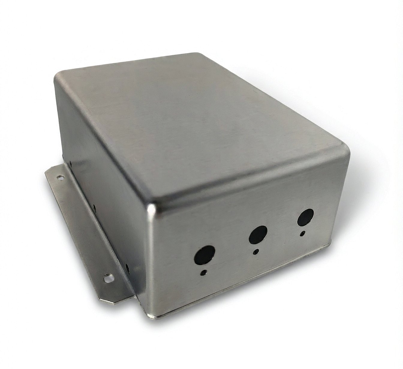
Every opening in this cover arrives after the shell is formed, and that is what makes it a drawn part rather than a plate
A perforated drawn cover plate is a one-piece deep drawn shell whose ports, fixing holes and mounting slots are pierced into the already-formed wall rather than into a flat blank, so the openings stay registered to the drawn form, the side wall stays continuous between them, and a closed face and an open edge leave the press as a single part with no corner seam to seal. The example shown here is typical of the family: a rectangular drawn cover with three round ports pierced in one long wall, a smaller locating hole beneath each of them, and two mounting ears at the open edge – a shape that would need a weld at every corner if it were folded from flat sheet, and a fixture to hold it flat if the holes were pierced first and the wall formed afterwards.
We coil-blank and progressively draw, pierce the openings on a following station against the finished form, and coin or restrike the flange face where the print calls for a sealing surface, with in-process checks sitting between stages rather than only at the end, on a press shop running 5-250 T mechanical and 250-500 T hydraulic presses with annealing ovens on site, CNC turning centres for secondary operations, and CMM inspection. Turned secondary features to +/-0.03 mm and as-drawn walls to +/-0.1 mm, with finer bands confirmed from capability data before quoting. Drawn depths to 150 mm, a 1,000-piece minimum per release, and a quotation returned within 24 hours against a drawing. Tools, fixtures and gauges are made in our own toolroom and held under your part number. This page is about where the openings can be placed, and why their position is a forming decision as much as a piercing one.
Why the openings are pierced after forming, not before it
Piercing the flat blank looks cheaper – one station fewer, one handling fewer – and it is the reason a lot of perforated covers arrive with oval ports and an assembly that no longer lines up. Four things happen to a hole between the blank and the finished shell:
- It moves. Metal flows inward as the shell is formed, and not by the same amount everywhere: on a rectangular draw the corner regions move less than the middle of a straight side. A round hole pierced into the blank travels with the sheet, and by the last station it sits somewhere other than where the print requires, usually further from the open edge and closer to its neighbour than designed.
- It changes shape. A side wall is stretched as it is pulled down through the flange radius, and a circle in that stretch zone comes out as an ellipse, worst exactly where the stretch is worst. Ports that have to accept a connector barrel, a grommet or a bushing do not tolerate that, and a slot opened up the same way is worse again.
- Its edge lands in thinned material. The wall is thinnest at the point of maximum stretch. A hole whose edge sits there starts from less material than the rest of the wall, and that is where a pierce-first part tears first – at the very place the customer least wants to see a failure.
- Its burr ends up on whichever face the die chose. Piercing always leaves a burr on one side, and piercing first means that side is whatever it happens to be, before the burr then goes through further forming that can fold it into the surface or smear it into the tool.
Where the draw allows a hole to sit
The useful rule is that a rectangular draw has two different flow regimes at once, and the openings have to respect both:
- The straight side is in tension. Material here is being pulled down from the flange and is thinning as it goes, so it is also where a misplaced hole distorts most. Openings belong below the flange radius and not across it, because the radius is a transition and a hole straddling a radius holds neither a true position nor a flat edge.
- The corner is in compression. Two sides feeding one corner builds excess material that wants to wrinkle, so the corner is the thickened and stiffest region of the shell. Small fixing holes can sit reasonably close to a corner; large ports generally cannot, because relieving the corner to open the port also removes the stiffness that is holding the shape square.
- Edge distance is measured on the finished part. Minimum distance from a hole edge to a formed edge, to the next hole, and to the open edge is quoted against the formed geometry, not against the blank – once the metal has moved, a figure taken on the flat is a figure about nothing.
- The mounting wants to live in the trim. Ears formed out of the trim line keep the drawn grain running through them and carry the fixing load better than a bracket added afterwards, which is why the mounting holes sit in formed ears rather than in a piece welded on later.
Burr direction, deburring and the face that has to seal
The most common reason a perforated cover does not seat is not the drawing, it is the burr. Four decisions belong on the print before any die steel is cut:
- Which face may carry the burr. Piercing pushes a burr out of one side, and where a cover closes against a gasket or a chassis face the burr belongs on the opposite side. That requirement sets the pierce direction, so it has to be known at tooling stage rather than discovered at assembly.
- What the pierced edge may look like. A pierced edge is not square all the way through – there is a roll-over where the punch enters and a break-out where it exits – and the permitted amount is a stated limit, not an assumption everybody shares.
- Which deburring route the part can survive. Thin-gauge drawn covers do not take kindly to aggressive grinding. Tumbling or vibratory finishing removes the burr from the pierced edges and rounds the outer trim edges in the same operation, which is why it is the usual answer for this family; brushed or hand-finished edges are separate operations with separate cost.
- That piercing makes chips. Every pierced opening produces slugs and swarf, and chips left inside a closed cover are contamination in an enclosure that nobody can easily inspect afterwards. A blow-out or wash after the piercing station is part of the route, not an optional extra.
Material, and what changes once the wall carries openings
Materials held include carbon steel, 304 and 316 stainless steel, aluminium and brass. Once the wall is pierced, three material behaviours matter more than they do on a plain closed cover:
- How much draw the material has before it needs annealing. As a working figure, the limiting draw ratios we plan around are 2.1-2.2 for DC04 drawing steel, 1.85-2.05 for 304 stainless steel and 1.80-1.95 for 5052 aluminium; past that the part needs an intermediate anneal, and the number of draws before annealing is decided by the deepest corner rather than by the average.
- What happens at the cut edge in service. A pierced edge is fresh metal with no protection on it. If the part is run from pre-plated or pre-coated coil, every pierced edge is bare, which means the coating does nothing at the place most likely to start corroding.
- How much the material has work-hardened before the punch arrives. Each drawing stage hardens the shell. That is useful in the finished part – a formed wall is stronger than the sheet it started from – but it also means the material being pierced after several draws is harder and less forgiving than material pierced after one, and edge quality follows from that.
- Aluminium takes a clean fine port edge and stays light where the port count is high; stainless steel holds its edge against wear and repeated mounting, which is a real advantage at the fixing holes on a cover that gets fitted and re-fitted.
Finishing: whether the coating comes before the piercing or after it
Finish is selected from the drawing – plating, coating, anodising or passivation – with the finish inspected alongside the dimensional report on the first article. The order of operations is the decision:
- Finishing after piercing puts protection on the cut edges. Zinc plating, anodising or passivation reach everywhere the pierce exposed bare metal, and it is the default recommendation wherever corrosion resistance is specified.
- Piercing after finishing happens when pre-finished coil is used, and it leaves every cut edge bare. It is cheaper – no second handling, no racking of finished parts – and it can be defended for indoor covers in dry service. It cannot be defended where the drawing specifies a salt-spray duration or an outdoor life.
- Features that have to fit are masked or sized for coating build-up. Coating adds thickness on both faces of a hole, so a fixing hole that has to accept a shoulder or a close-fitting pin is either masked, machined after coating, or called up at a size that accounts for the coating.
- Flatness has to be stated before and checked after. A flange face that seals is coined before finishing and measured after it, because plating and anodising do not flatten anything and residual stress released unevenly during processing will show up on the face that mattered.
Tolerance, and the datum the pierced holes should be measured from
Turned secondary features at +/-0.03 mm and as-drawn walls at +/-0.1 mm is the stated structure, and pierced positions sit between those two bands, held by the piercing die rather than by how the metal flowed. That makes the datum the useful question:
- Dimension from the feature the mating part locates on. A cover that bolts to a chassis should have its fixing holes measured from the same features the chassis uses, and those are usually the two mounting holes themselves rather than an outside edge that the drawing process holds loosely.
- Drawn profiles and pierced positions are different tolerance classes. The centre distance between two pierced holes is repeatable because the die sets it; the outline of the drawn wall around them follows the drawn band. Putting every feature in one tolerance class to make the drawing look tidy is what makes quotations come back expensive.
- A port is not a clearance hole. A clearance hole for an M4 screw and a port that has to grip a component are different tolerances punched into the same wall, and they should not be measured, toleranced or priced the same way.
Eight things to state on the drawing
Eight things, and the first three are the ones usually missing when the enquiry arrives:
- The pierce direction and the permitted burr face, per opening, together with whether the requirement is “no burr” or an actual stated limit.
- The datum each opening is measured from, and whether that datum is another opening or a formed feature.
- Minimum edge distance – hole to formed edge, hole to hole, hole to open edge – all against the finished part.
- Tolerance per feature class rather than one blanket note: mounting holes, ports and drawn profile each get their own band, and the band you actually need is usually looser than the one on a template drawing.
- Material grade and temper, and whether the starting stock is bare, pre-plated or pre-coated, because that decides whether your cut edges will be protected.
- Finishing order – before or after piercing – which surfaces are masked, and whether dimensions are stated before or after finish.
- Flatness on any sealing face, given as a flatness callout against a support condition rather than as the word “flat”.
- Quantity and release pattern, because tooling is built around it: minimum 1,000 pieces per release, with the die re-cuttable against the approved drawing and ownership confirmed on the quotation.
Does this part have to be drawn, or would a plate do it?
Worth settling before the drawing goes out, because it changes the part count. A flat perforated plate with a folded or welded rim will do the same job where the wall is shallow and where nothing has to stay registered to a formed feature, and at small quantities it will be cheaper. It stops being cheaper the moment the wall is deep enough that the corners have to close, because then the seam has to be sealed and finished, and it stops working altogether once two ports have to stay coaxial with each other across a formed corner. Establishing which route wins is a better conversation at enquiry than after the first samples refuse to assemble.
If you are weighing drawing against machining or welding for this geometry, the guide to deep drawn covers sets out where each route wins, and the page on custom-tooled square and rectangular drawn covers goes into what the corner and side flow does to tooling cost. The full Precision Deep Drawn Parts range is linked from the overview page.
Specifications
| Item | Perforated Drawn Cover Plate |
|---|---|
| Brand | AUNOV |
| Designing | DFM feedback accompanies the quotation, so surprises are caught before the die is cut. |
| Tooling | Dies, fixtures and gauges are made in our own toolroom, so a die can be re-cut against the approved drawing, and ownership is confirmed on the quotation. |
| Samples | Prototype and pre-production samples are provided against the drawing, so any deviation is corrected at sample stage, and mass production is gated on that approval. |
| Materials | Materials held include carbon steel, 304 / 316 stainless steel, aluminium and brass; special grades are sourced to the drawing when volumes justify. |
| Surface finish | Finish selected from the drawing: plating, coating, anodising or passivation; the finish is inspected with the dimensional report on the first article. |
| Processing | Coil blanking and progressive drawing, coining on the final station where the print calls for it; in-process checks sit between stages, not only at the end. |
| Equipment | Press shop running 5-250 T mechanical and 250-500 T hydraulic presses, annealing ovens on site, with CNC turning centres for secondary operations and CMM inspection. |
| Tolerance | +/-0.03 mm on turned secondary features, +/-0.1 mm on as-drawn walls; finer bands confirmed from capability data before quoting. |
| Delivery terms | Terms are FOB by default, with CIF and DDP quoted on request and freight priced to your door. |
Related Products



Frequently Asked Questions
Why are the openings pierced after drawing instead of before it?
A hole pierced into a flat blank travels with the metal as the shell forms, and where the side wall is stretched it loses its round shape, so the finished port arrives off position and oval. Piercing against the finished form keeps every opening registered to the drawn wall, keeps the ports round, and lets the burr be put on the face nothing has to seal against.
How close can a pierced hole sit to a formed corner?
Closer than to a straight side, because the corner of a rectangular draw is in compression and the material there ends up thicker, but a large port still does not belong there – relieving the corner to open it removes the stiffness that is holding the shape. Small fixing holes work near a corner; ports belong in the side wall, clear of the flange radius.
Do the pierced edges get corrosion protection?
Only if the finishing follows the piercing. A pierced edge is bare metal with no coating on it at all, so a cover run from pre-plated or pre-coated stock has unprotected edges exactly where corrosion usually starts, while plating, anodising or passivation carried out after piercing covers every cut edge on the part.
What tolerance can pierced hole positions be held to?
Tighter than the drawn profile and looser than a turned feature, because centre distances between two pierced holes are set by the die rather than by how the metal flowed. The real control is choosing the datum each opening is dimensioned from – normally the feature the mating part locates on – rather than tightening every hole to the same band.
Request a Quote for This Part
Send a drawing or sketch — get material advice, tooling cost and a per-piece price within 24 hours (working days).