
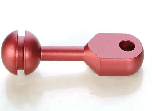
A knurled standoff pin looks like the simplest possible part: a small rod with a knurl on it. It is actually a locating element with four requirements pulling in different directions – it has to be stiff, it has to be hard, it has to resist rotation, and it has to fit a hole accurately – and the knurl is where two of those four requirements fight each other most visibly.
The knurl on a standoff is usually a grip so the pin can be installed and removed by hand without a tool. Which means the knurl is a handling feature, and every dimensional decision about it follows from that: it has to be positive enough to turn, and loose enough that the operator can still feel whether the pin is fully seated.
What the pin is holding apart, and what that means for its stiffness
A standoff’s job is to hold a spacing. That means it is very often a compression member, and compression members fail by buckling long before they fail by crushing. Buckling resistance scales with the second moment of area, which scales with the fourth power of the radius, so on a small pin the diameter is the dominant variable and there is a very strong argument for making it as large as the design allows.
Three things follow:
- Diameter is nearly free stiffness. Doubling a pin’s diameter increases its area four times and its second moment of area sixteen times. Where the pin is the weak link and the space is available, this is the cheapest improvement available and it costs nothing but envelope.
- Length is nearly free failure. Buckling resistance falls steeply with length, so a pin’s slenderness ratio – length divided by radius of gyration – is the number that decides whether it is a structural member or a spacer. This is the calculation that determines whether the pin needs to be steel or can be a lower-strength alloy.
- End condition matters as much as diameter. A pin that is free to rotate at one end has a much lower buckling load than one that is clamped. Where the pin goes into a threaded hole it is effectively clamped at that end, and that changes the design entirely – and it changes the knurl’s purpose, because a threaded pin does not need to be hand-turned.
So the first question on a knurled standoff is: does it also have a thread? A pin that is threaded into one end and knurled for hand-turning at the other is a very common and very sensible arrangement, and in that case the knurl’s job is purely to get enough torque to start the thread without a wrench. A pin that is press-fit at both ends and knurled is a locating pin, and the knurl is for removal.
The knurl’s conflict with accuracy
Here is the tension that makes this part worth writing about. The knurl is cut into the pin’s diameter. Therefore:
- The knurl raises the pin’s diameter at the tip. A knurl at 0.25 mm depth makes the pin’s tip diameter about 0.25 mm larger than the root. If the pin goes into a close-fitting hole, the hole has to be sized for the knurl’s tip, and then the pin’s rotational accuracy is set by a knurl – which is by definition an imprecise feature.
- The knurl lowers the pin’s effective stiffness. Cutting a pattern into a small-diameter pin removes material from the section where it is most effective. A knurl on a pin that is carrying a buckling load is a stress-relief feature as well as a grip, and on a heavily loaded pin the knurl band should be kept away from the middle of the span where the bending moment is highest.
- The knurl raises the surface roughness of the grip and makes the pin harder to hold in a fixture, which matters if the pin is machined after knurling.
The resolution used in practice is straightforward and worth stating as design guidance: put the knurl on a dedicated band at one end of the pin, not over the whole length. The band is where the operator’s fingers go and where the torque is applied; the shank below it stays plain, stays full diameter, and keeps both its stiffness and its fit accuracy. This is also why the knurl’s axial extent belongs on the drawing as a stated dimension.
The pin’s fit, which is the accuracy requirement
A standoff that locates something has to hold that something in position, and that is a fit between the pin and the hole – or between the pin and the thread – rather than a free fit.
- For a press-fit pin, the pin’s diameter and roundness and the hole’s diameter and roundness together define the location. The knurl band should be outside the hole’s depth entirely, so that the fit is defined by the plain shank.
- For a threaded pin, the thread’s pitch diameter and class are the specification, and the knurl needs to be sized so that the operator can generate enough torque to start the thread. A knurl that is too fine will slip; one that is too coarse will chew the thread on the first attempt. This is a feel-based decision that works much better if the knurl’s specification is given than if the shop chooses one.
- Roundness is worth more than size on a small pin. A pin at the correct diameter but out of round will locate the part at one angular position and slop at another, and on a short standoff the effect at the far end is the pin’s diameter multiplied by the length divided by the engaged length – which means slop is amplified.
A standoff is a short decision about strength and environment
Carbon steel, 304 and 316 stainless steel, aluminium and brass are all held, with special grades sourced when volumes justify. On a standoff the material decision is short and mostly about strength and environment.
- Carbon steel is the default for a structural standoff and it machines and knurls well. It needs protection against corrosion, and a plating here is a wear and corrosion decision rather than a dimensional one – with the usual caveat that the plating changes the pin’s diameter and therefore its fit.
- Stainless Steel where the environment demands it, and note the specific standoff problem: an aluminium component and a stainless steel standoff in the same hole is a galvanic couple in a crevice, and the crevice is exactly where the water sits. If an aluminium part has a stainless steel pin in it, the pin hole should be masked or the pin isolated.
- Aluminium is fine for a non-structural standoff, and its lower modulus means it should be larger for the same stiffness. Knurling is easy and anodising is straightforward, which makes it a good pairing for an appearance pin.
- Brass is used where a non-sparking requirement exists, or for a light-duty pin where galling against the mating part is a concern. It knurls well and it is soft, so it will deform if it carries a real load.
The pin’s ends, which are usually the real problem
Two details that get less attention than the knurl and that cause more returns.
- The chamfer at the insertion end. A standoff that is press-fit needs a lead chamfer, and a knurled pin’s working end usually has a knurl right up to the edge, which makes insertion difficult and can damage the mating hole’s chamfer. A lead chamfer on a knurled pin has to be machined before the knurl, and it should be specified.
- What the far end is doing. If the far end locates into another hole, it has its own fit requirement and the pin’s straightness becomes critical – a bent standoff will locate its two ends in two different directions. Straightness is worth specifying on any pin over a certain length, and it is worth measuring on a CMM rather than assumed from a machining operation.
- Thread relief. Where the knurl band meets a threaded section, the knurl’s end must not overhang the thread’s first engaged turn. A knurl that runs into the thread will strip it.
Shank, knurl band and end features belong to a single setup
Turn-mill machining with critical diameters finished in one setup is the correct route, and on this part the one-setup rule is about the relationship between the pin’s plain shank, its knurl band, and its end features. A pin that is re-chucked between knurling and machining its ends will not have a straight relationship between them.
- Knurl after the plain shank and the ends are finished, and before any measurement that depends on the shank. The sequence should be on the routing sheet because a knurl operation moved earlier will disturb the finished shank’s surface.
- Stainless Steel needs care. It work-hardens, and an interrupted knurl leaves a smeared pattern rather than a cut one. A continuous knurl pass is the requirement.
- Deburring on the knurl’s edges, on the chamfer, and on the thread’s entry.
- Laser marking is available and on a small pin it is the most sensible way to identify it – a stamped or engraved mark on a knurled standoff would either fall in the knurl or damage the hand grip.
On a knurled standoff, the plain shank carries the tighter band
+/-0.01 mm on ground diameters, with GD&T from the print, and finer bands confirmed from capability data before quoting. On a knurled standoff the allocation is:
- Plain shank diameter and roundness at the tighter end, since this is the fit and the stiffness. Not the knurl.
- Knurl depth and pitch to their own bands, measured on a first article and periodically, always on the same basis.
- Length and straightness, with straightness specified if the pin locates at both ends.
- Thread class and form where the pin is threaded, gauged.
- Chamfer angle and diameter, stated, since the chamfer is functional on insertion.
Inspection in practice: shank diameter and roundness on the CMM, knurl depth on a first article and periodically, thread gauging where threaded, straightness where it locates at both ends, and a functional check – fit the pin into its mating part and confirm it seats without shimming. On a part whose job is to hold something in position, the assembly check is the most informative inspection available and it takes seconds.
Carrying load, or spacing
Is the pin meant to carry load, or is it a spacer? This single question decides the diameter, whether the material needs to be steel, whether the knurl has to be kept off the middle of the span, and whether the tolerance effort should go on the shank or somewhere else. A pin that carries no load can be light, small, aluminium, and loosely specified on everything except its length. A pin that carries load is a column, and its slenderness is a calculation rather than a preference – and the knurl, which is the feature that gives the part its name, is a stress relief cut in the middle of that column. On many designs the correct answer is to move the knurl to one end, increase the diameter slightly, and reduce the specified length tolerance by tightening one end rather than the other. It costs nothing to ask that question at enquiry stage, and it changes the part.
CNC Machining Parts is the parent range for parts like this one; the overview page gathers the tooling logic, finishing options and tolerance notes that apply across the family.
Specifications
| Item | Stainless Steel Knurled Standoff Pins |
|---|---|
| Brand | AUNOV |
| Designing | Made to your 2D/3D drawings (PDF, DWG, STEP, IGS) – samples are reverse-measured into a controlled drawing; the agreed version governs every later batch. |
| Tooling | Dies, fixtures and gauges are made in our own toolroom, so no tooling step is outsourced, and ownership is confirmed on the quotation. |
| Samples | Pre-production samples come with a full inspection report, so the sample is retained as the master, and later batches are gauged back to the signed sample. |
| Materials | Carbon steel, 304 / 316 stainless steel, aluminium and brass are all held in stock; special grades are sourced to the drawing when volumes justify. |
| Surface finish | Surface treatment matched to the duty: plating, coating or polishing; masking and laser marking available where needed. |
| Processing | Turn-mill machining, critical diameters finished in one setup; first articles verify the whole flow before the run is released. |
| Equipment | CNC turning centres with bar feeders and 3-/4-axis machining centres, backed by CNC turning centres and a climate-controlled inspection room. |
| Tolerance | +/-0.01 mm on ground diameters, with GD&T taken from your print; finer bands confirmed from capability data before quoting. |
| Delivery terms | Freight, Incoterm and payment term are confirmed on the order: FOB, CIF or DDP, T/T or L/C. |
Related Products



Request a Quote for This Part
Send a drawing or sketch — get material advice, tooling cost and a per-piece price within 24 hours (working days).