
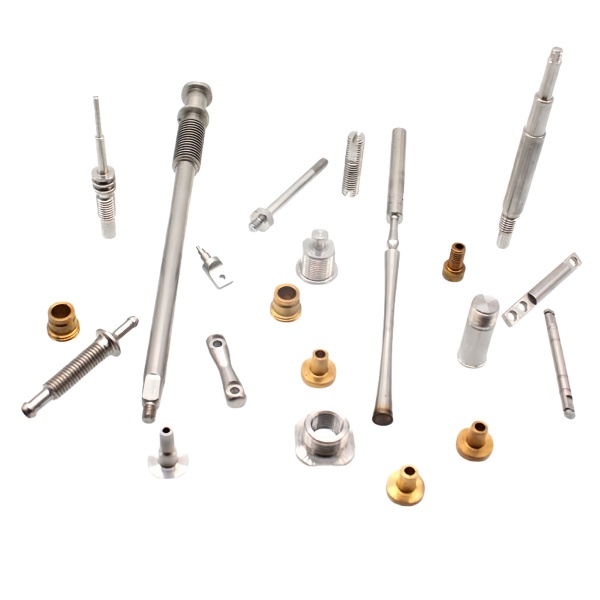
The Stainless Steel CNC Machined Probe Needles with Brass Tips family is the slenderness extreme of our turning work: needle-scale parts where the length-to-diameter ratio drives every process choice, and where a stainless steel body is joined to a brass tip that must land concentric, strong and electrically sound. On parts this thin, deflection is not a defect category – it is the default condition of the material, and the whole engineering effort goes into managing it. This page covers the whip problem on slender turning, the joint between the two metals, the tip geometry itself, and the verification that a needle shipment carries.
Slenderness is the first engineering number on a needle, before any dimension
On a turned part, the ratio of unsupported length to diameter decides what is physically possible. A needle at 20:1 or higher cannot be cut like a bushing: the cutting force that a stout part ignores will deflect a slender one by hundredths of a millimetre, and the deflection feeds back into the diameter, producing tapers and lobes that no amount of careful programming removes. The countermeasures are mechanical – support the material at the point of cutting or reduce the force that acts on it.
- Swiss-type turning with the guide bush supporting the bar at the cut is the primary route: the part never hangs free while metal is being removed, and diameters stay honest along the whole length.
- Where the geometry exceeds what one guide position can cover, steady rests carry the work at intermediate stations, and the rest pressure itself becomes a controlled parameter – too little support lets the part sing, too much bows it permanently.
- Cuts are taken light and sharp with high positive rake, because the cure for deflection is force reduction, and a dull edge is a force multiplier on a thin part.
- We quote slenderness honestly: above certain ratios the achievable tolerance degrades by physics, and a print asking for shaft-grade roundness on a 30:1 needle without support strategy is a print asking for a conversation.
The same logic governs handling. A needle that survived the machine can be bent by a thumb and forefinger at packing, so handling and transport fixtures are part of the process plan, not an afterthought.
Joining a brass tip to a stainless steel body without melting either
Dissimilar-metal joints on needle scale have to solve three problems at once: mechanical strength at a small cross-section, electrical continuity where the tip is a contact, and thermal discipline – brass melts close to the temperatures where stainless steel’s structure is unharmed but the joint’s neighbourhood distorts, and any overheating shows up as softened brass or a heat-tinted stainless steel surface that later corrodes. Brazing with a silver filler is the standard answer because it wets both metals at temperatures well below either melting point; the fit between the parts controls the joint quality more than the torch does, because capillary action fills a gap of a few hundredths and refuses a gap of a few tenths.
How we run the joint:
- The mating diameters are machined with the braze gap in mind – roughly 0.02-0.08 mm depending on size – and the gap is a specified dimension in our process, not a coincidence of two prints.
- Flux and heat are applied to wet both surfaces fully before the filler is drawn in; a starved joint passes a visual check and fails on pull strength months later.
- Post-join cleaning removes flux residue completely, because aggressive residues attack the joint line and are the classic cause of a corrosion failure at exactly the place the customer inspects first.
- The joint’s heat effect on the stainless steel side is checked where the duty demands it – a thin section near the joint can lose enough from the heat-affected zone to matter, and passivation afterward restores the surface but not the metallurgy.
Electrical continuity across the joint is verified where the needle is a sensing element, and the contact resistance criterion belongs in the control plan, not in folklore.
Tip geometry is a contact patch problem, and the patch is tiny
The business end of a probe needle is defined by a radius or a small taper, and at that scale the geometry is the function. A tip radius of 0.05 mm is not “sharp” – it is a specified contact area that determines current density, insertion force and wear life all at once. A tip that is 20% oversize on radius changes the contact patch by 40% and the measured resistance with it; a tip with a torn or burred edge from a worn tool scratches the surface it probes instead of touching it cleanly.
- Tip forms are turned with tool life limits set aggressively short – the difference between a good tip and a burred one is one insert’s worth of wear, so we replace the edge on count, not on visual evidence.
- The tip transition – where the taper meets the radius – is inspected on the first article optically at magnification, because that blend is where a programmed path most often leaves a step.
- Brass tips intended as contacts get their finish verified as well as their form, since oxidation and machine smearing both raise contact resistance measurably.
- Where needles are batch-verified electrically, a resistance measurement is the cheapest full-population functional test available, and we encourage it as a shipping gate.
Straightness over the working length is a needle’s real dimension
A needle can hold every diameter in tolerance and still be unusable because it bows. Straightness over length is governed by the same stress logic as any turned part but amplified: released stress from bar drawing, residual stress from the cut itself, and the braze joint’s thermal contraction all bend thin parts, and the bending happens after the diameters are already correct. The cure is sequencing and support, plus an honest measurement in the free state.
- Roughing removes bulk stress early; finishing runs in one uninterrupted light pass along the full working length so no differential stress is introduced at the end.
- The braze is done before any final straightness-critical finishing on the body where the sequence allows, so the joint’s contraction is corrected by the last cut rather than shipped inside the part.
- Free-state straightness is measured by rotation – rolling the needle on a flat or rotating it between centres under an indicator – and the criterion is stated on the report in total indicator terms.
- Parts are packed in v-groove trays or tubes that support along the length, because a needle straight at inspection can be bent by the inside of a courier van, and the packing is our last process step, not a logistics detail.
How we verify tip form and joint integrity on probe needles
Verification on this family is magnification- and function-heavy because the critical features are below the reach of contact measurement. Each release ships with:
- Tip form inspection at magnification on a sampling plan – radius, taper blend and edge condition judged against the first-article reference, with defects categorized rather than merely counted.
- Concentricity of tip to body checked on the first article by rotation under an indicator, since a probe that wobbles is a probe that misses its target.
- Straightness in the free state reported as total indicator reading over the working length, with the support method stated.
- Joint evidence – pull or shear testing of samples from the braze lot where the duty is mechanical, and contact-resistance measurement across the joint where the duty is electrical, reported as values against criteria.
- Diameter and length on the sampling plan, with slender-part measurements taken at defined stations so taper shows as data.
- Material and process traceability – stainless steel heats, brass lots, braze lot and passivation record for the stainless steel surfaces, all under the release’s part numbers.
The first-article report and reference photographs are archived so repeat orders reproduce the approved tip, and the packing method is written into the control plan because on this family it is part of quality.
The CNC Machining Parts range is the parent for parts like this one; tooling logic, finishing options and tolerance notes for the whole family are gathered on its overview page.
Specifications
| Item | Stainless Steel CNC Machined Probe Needles with Brass Tips |
|---|---|
| Brand | AUNOV |
| Designing | Send the drawing, or a probe sample we can measure, a manufacturability review comes back with the quotation. |
| Tooling | Dies designed and built in our own toolroom, each die held against your part number. |
| Samples | Samples for approval come with dimensional data and material certification. |
| Materials | 304 / 316 stainless steel is the primary stock for this part, alongside carbon steel (SPCC / DC01), aluminium, brass and copper, with grade selection confirmed at drawing review. |
| Surface finish | Surface treatment per the drawing: plating, e-coat, powder coating, anodising, passivation, as called out on your print. |
| Processing | Stages of deep drawing, annealed in line where the draw ratio calls for it, then pierced and CNC-machined under our own roof. |
| Equipment | Press capacity from 5 to 500 T across mechanical and hydraulic lines, CNC turning centres, climate-controlled CMM room. |
| Tolerance | +/-0.1 mm as-drawn, +/-0.03 mm after machining. |
| Delivery terms | FOB is standard; DDP offered for EU and US, T/T or L/C, D/P on repeat business, blanket orders and call-offs supported. |
Related Products



Request a Quote for This Part
Send a drawing or sketch — get material advice, tooling cost and a per-piece price within 24 hours (working days).