
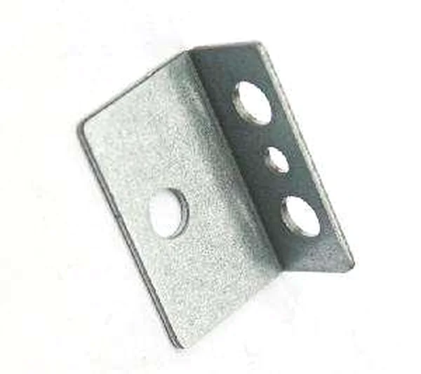
A triangular gusset is a bending problem before it is a stiffness problem
Anyone who has watched a shelf corner sag learns the same lesson in a different order than the engineer who calculated it: the corner did not sag because the steel was too thin, it sagged because the load arrived as a moment rather than as a force. A triangular gusset angle bracket exists to convert one into the other. It takes a load that would otherwise bend a shelf rail or a frame member about its weak axis and redirects it into tension and compression along two legs that are already good at carrying those. Everything about how this part is made — the blank, the fold, the hole pattern, the coating — follows from that single job.
AUNOV stamps the triangular gusset angle bracket from 2.0 mm pre-galvanized steel on press-brake and stamping equipment, holding hole position to ±0.10 mm and bend angle to ±0.5°, with critical dimensions gauged 100%. That tolerance pair is not arbitrary, and it is worth unpacking both numbers, because they fail in completely different ways. Hole position drives whether the bracket assembles at all. Bend angle drives how much of the load the bracket actually collects. A bracket that is 1° off in bend angle can be perfectly within hole position tolerance and still be useless, because its bearing face no longer sits flat against the frame it is meant to brace.
Why the gusset is a triangle and not a rectangle
The diagonal is doing the work. In a right-angle corner brace, the highest bending moment occurs at the inside corner, exactly where a rectangular plate would have the least material and the sharpest stress concentration. A triangular profile removes material where the bending moment is low and leaves the full depth where the moment peaks. The result is roughly constant stress along the hypotenuse instead of a spike at the re-entrant corner.
That has a direct manufacturing consequence that is easy to miss at the quotation stage. The hypotenuse of a stamped gusset is a cut edge, and cut edges on 2.0 mm steel carry a burr. If the burr side happens to be the face that seats against the frame, the bracket will rock on its own burr, and the bolted joint will never develop the friction the design assumed. We control burr direction as part of the die design and call it out on the first-article report, because it is a functional attribute of this part and not a cosmetic one.
- The base leg carries the bolt load and must stay flat — flatness here is a bearing requirement, not a finish requirement.
- The upright leg transfers load into the frame member and often needs to sit inside a channel, so its width is a fit dimension.
- The hypotenuse is the load path itself; gouges, shearing scars or a coarse burr along it become crack initiation sites under repeated loading.
- The inside corner radius at the fold is where the material is thinnest after forming, so it is the natural location for the first fatigue crack.
Pre-galvanized steel and what the coating does to a fold
Pre-galvanized sheet is supplied already coated, which is a large practical advantage: the cut edges and pierced holes inherit the corrosion protection of the surrounding zinc, and there is no post-plating operation to schedule, no racking marks, and no risk of hydrogen embrittlement. The zinc layer is thin, typically in the range of a 14 to 20 micrometre coating mass designation depending on the specification, and it is ductile enough to survive a bend.
What it does not survive quietly is a tight bend radius combined with a sharp tool. The zinc is a separate material with its own ductility, and at the outside of a tight bend it will craze or flake before the steel underneath reaches its own forming limit. That flaking is a cosmetic complaint at first and a corrosion complaint two years later, because it exposes bare steel in exactly the most stressed region of the part. Three levers control it, and all three belong on the drawing review:
- Minimum inside bend radius. For 2.0 mm pre-galvanized steel, an inside radius of one material thickness is the practical floor for a press-brake operation; below that, coating damage and micro-cracking in the steel both become likely. A radius of 1.5 to 2.0 times thickness is a safer default when the part will see cyclic loading.
- Bend direction relative to the rolling direction. Bending across the rolling direction is more forgiving than bending parallel to it. When a part has several bends in different orientations, one of them will be the difficult one, and it should be identified before the die is cut.
- Die radius and surface condition. A polished die radius with adequate clearance reduces the tensile strain on the outer fibre. Clearance for 2.0 mm steel is typically set at 8 to 12 percent of thickness per side; too little clearance raises punch load and galling, too much produces a rounded, poorly defined corner.
Retained austenite, springback, and why ±0.5° is honest
Every bend springs back. The steel deforms elastically first, then plastically, and when the punch withdraws the elastic portion recovers. On 2.0 mm steel with a moderate radius, springback is usually between 1° and 3° of the formed angle, and it varies with sheet thickness, yield strength, and the actual radius achieved. This is why a bend tolerance of ±0.5° is a real achievement rather than a loose one: it means the die has been compensated for springback based on measured coupons from the actual material lot, not on a table.
Springback also has a less obvious consequence for the gusset. If the base leg springs to 89.5° instead of 90°, the top edge of the base leg lifts by roughly 0.9 mm over a 100 mm leg. Bolting the bracket down will pull it flat, but the bolt then carries a permanent preload fighting the bracket, and the joint is pre-stressed before it ever sees service load. That is why bend angle belongs on the first-article inspection report as a measured value, not simply as a pass or fail.
Hole position at plus or minus 0.10 mm, and where that budget goes
A ±0.10 mm hole position tolerance sounds generous until you add up the contributors. Within a single stamped part, the hole is located by the die’s punch and pilot arrangement, and the pilot is positioned relative to the bend. The chain runs blank locator, first bend, second bend, then hole pierce — and any position error introduced early is carried downstream. On a gusset bracket with two bends, the practical sequence matters enormously:
| Process sequence | Effect on hole position | When to choose it |
|---|---|---|
| Pierce after forming, holes referenced to the formed leg | Holes stay correct relative to the surface that mates with the frame | Default for a bracket whose bolt holes must line up with a fixed frame pattern |
| Pierce before forming, holes referenced to the flat blank | Cheaper tooling, but every hole moves with the bend’s springback and with the material’s stretch near the fold | Only when holes are far from the bend and position is not critical |
| Pierce before, re-strike or coin after | Recovers position to roughly ±0.05 mm at the cost of an extra station | High-volume brackets where the frame hole pattern is fixed and unyielding |
Notice the asymmetry in that table. It is almost always cheaper to design the bracket so that its critical holes can be pierced after forming than to hold a tight pre-form hole position. A drawing that specifies a single global hole tolerance without saying which state it applies to is asking the toolroom to guess, and the guess will be resolved in favour of the cheaper sequence.
Load paths through the bracket, and the two places it fails
Field returns for this class of bracket cluster into two failure modes. The first is cracking along the hypotenuse or at the inside corner of the fold, which indicates a fatigue problem and usually traces back to a burr, a shearing scar, or an undersized inside radius combined with a load that reverses. The second is elongation of the bolt holes or loosening of the joint, which is a bearing and preload problem rather than a strength problem.
Both are addressable without changing material thickness, which is the expensive lever:
- Increase the inside bend radius so the outer fibre strain stays below the material’s forming limit; this shifts the crack initiation away from the corner.
- Deburr the hypotenuse to a controlled radius rather than leaving a sharp cut edge, and specify that the burr faces away from the mating surface.
- Add a washer or increase the bolt-bearing area under the head if the hole is elongating; the steel’s bearing strength is usually adequate, the contact pressure under the head is what is excessive.
- Keep the hole at least two material thicknesses from any bend line; a hole closer than that will distort during forming because the bend’s plastic zone reaches it.
Inspection and what the report should carry
With critical dimensions gauged at 100 percent on this part, the first-article report does more work than usual. We measure and record the two bend angles independently, the distance between the base leg’s hole centres and the frame datum edge, the perpendicularity of the upright leg to the base leg, the inside bend radius at each fold, and the burr condition along the hypotenuse. Flatness of the base leg is checked on a surface plate because it is the attribute that determines whether the bracket sits quietly or rocks.
Where a customer supplies their own frame drawing with a fixed bolt pattern, we also build a check fixture that mimics the mating surfaces. A fixture catches error that individual dimensions miss, specifically the compounded effect of two bend angles and one hole pattern all drifting the same way. This is the difference between inspecting a part and inspecting a part’s function.
Tooling, repeat orders, and the economics of a small bracket
Tooling for this bracket is held under the customer’s part number and can be re-cut from the original design data, which matters more than it sounds. Gusset brackets are frequently revised — a frame changes, a shelf depth changes, a hole moves 4 mm — and a die that can be re-cut from stored data costs a fraction of a new die set. First-article samples ship with a full inspection report so the part is proven before volume production, and subsequent lots are gauged back to the signed sample.
Because the part is small and simple, the economic decision is rarely about the piece price. It is about the die amortization curve, the minimum economic lot, and whether bend sequencing allows one die to produce more than one variant. A bracket that shares its hole pattern and bend lines with a sibling part can usually be produced from the same die with a change of blank or an added station, and that is worth designing for deliberately. If you send us both drawings together, we will tell you whether they can share tooling before either is quoted.
Eight lines a gusset bracket drawing should carry
- Material grade and thickness with the coating designation, for example pre-galvanized steel at 2.0 mm with a stated coating mass.
- Inside bend radius at each fold, not just the external angle.
- Which holes are functional — that is, which ones mate with a fixed pattern — so the toolroom can pierce those after forming.
- Bend angle tolerance and the measurement method, so the springback compensation is verifiable.
- Burr direction requirement relative to the mating face.
- Flatness requirement on the bearing leg, with the measurement reference.
- Loading direction and whether it reverses, which decides whether the inside radius is a comfort or a fatigue requirement.
- Whether the part is one of a family that should share tooling.
Going to a heavier gauge trades corner cracking for hole elongation
Can the bracket be made in a heavier gauge?
Yes, and we would usually recommend it only if the failure is hole elongation rather than corner cracking. Going from 2.0 mm to 2.5 mm raises stiffness and bearing area but also raises the minimum bend radius and the press tonnage required, which moves the part into a different tool class. Often a radius increase and a washer solve the same problem for less.
Is pre-galvanized steel as corrosion resistant as post-galvanized?
For cut-edge protection, yes, and sometimes better, because the zinc on the surface galvanically protects the exposed cut. What it lacks is the ability to build a thick coating, so severe environments may call for a heavier coating specification or a different base material. Tell us the environment and we will quote against it.
How many bends can a single part carry before the tolerance chain gets unreasonable?
As a rule of thumb, keep the number of bends whose angle the assembly depends on to two. Beyond that, each additional bend multiplies the accumulated error and you are better off redesigning the joint or moving the feature to a machined operation.
What lead time should be expected for a first order?
The die is the lead item, not the parts. A first order runs from drawing approval through die build, first-article inspection, sample sign-off, then volume. Subsequent orders skip the die portion entirely and are governed by press availability and the coating or finishing operation if any.
Parts like this one sit under the Custom Metal Stamping Parts range, whose overview page gathers the tooling logic, finishing options and tolerance notes shared across the family.
Specifications
| Item | Stamped Triangular Gusset Angle Bracket |
|---|---|
| Brand | AUNOV |
| Designing | Made to your 2D/3D drawings (PDF, DWG, STEP, IGS) – the die is planned around your critical features, and the approved print governs every later batch. |
| Tooling | Tooling is held under your part number, so a die can be re-cut from the original design data, and maintenance is tracked against the part number. |
| Samples | Pre-production samples come with a full inspection report, so the stamped triangular gusset bracket is proven before volume production, Later batches are gauged back to the signed sample. |
| Materials | pre-galvanized steel, 2.0 mm; mill certificate and heat-number traceability supplied with the first article. |
| Surface finish | pre-galvanized; alternatives quoted against the drawing. |
| Processing | press brake + stamp – a triangular gusset bracket that braces shelf and frame corners. |
| Equipment | Mechanical presses 5-250 T with progressive dies; secondary ops run on CNC turning centres, inspection on the CMM. |
| Tolerance | ±0.10 mm hole position; ±0.5° bend; critical dimensions 100% gauged. |
| Delivery terms | FOB as standard, with DDP offered for EU and US addresses; T/T or L/C, sea or air freight quoted to your door. |
Related Products
Request a Quote for This Part
Send a drawing or sketch — get material advice, tooling cost and a per-piece price within 24 hours (working days).