
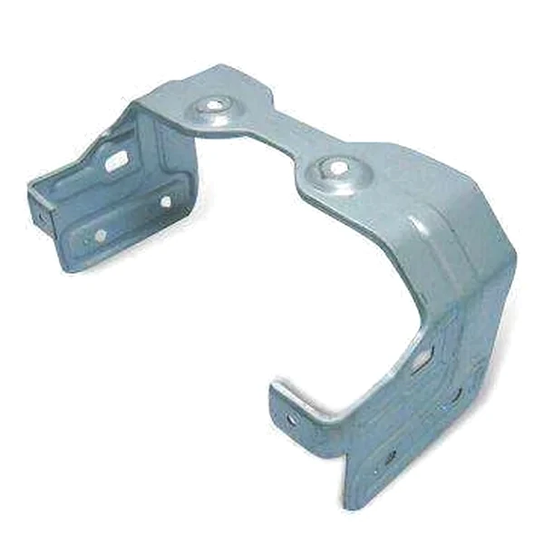
Internal width on a U bracket is set by the bend, not the pierce
This clamp bracket wraps a pipe or conduit run, and the dimension that matters functionally is the internal width, called to ±0.10 mm. That tolerance is not held by the piercing operation at all.
The internal width of a U is the sum of two flat widths plus two bend allowances, and every one of those terms moves. The flats are pierced to a tolerance. The bend allowances depend on the inside radius and on how much material is consumed in each bend. The bend angles have their own springback.
- Two bends, not one — the width is the sum of two bend allowances. The tolerance on the width is therefore a tolerance on two forming operations, not one. On a 2.0 mm U with two 90° bends at a6 mm inside radius, each bend allowance is around 2.6–2.9 mm.
- Leg parallelism — called to ±0.5°. At a 40 mm leg, half a degree is roughly 0.35 mm of tip movement, which changes the effective internal width at the mouth without changing it at the base.
- Symmetry — the useful measurement is width at the base and width at the mouth. If those two differ, the legs are not parallel, and a bracket that measures ±0.10 mm at the base can still not clamp.
- Springback opens the U — both legs spring back slightly outward, so the internal width at the mouth ends up marginally wider than at the base unless the tooling compensates for it.
Two bends are harder than one, and the second one sees a stiffer part
The obvious route for this bracket is a single progressive die that pierces and forms both legs in one stroke. The complication is that the two bends do not form independently. When the first leg forms, the part becomes significantly stiffer, and the second bend then forms against that stiffer condition.
This produces a bracket that is systematically asymmetric if the tooling assumes symmetry, and the asymmetry is built into the tool rather than into the material.
- Form both legs in one station — a two-out-of-plane forming tool can do this, and it keeps the material condition identical for both bends. More tooling cost, better symmetry.
- Two stations — cheaper tooling, but the second bend forms on a part that the first bend has already stiffened. Compensation has to allow for that, and the allowance differs from a flat-part calculation.
- Rotate the part between bends — forming the second bend with the part rotated changes which fibre is stretched and often improves the result, at the cost of a more complex transfer.
- Compensation record — whichever route is used, the achieved width and leg angle at first article become the recorded targets, and the tooling is set to reproduce them rather than to the theoretical values.
The compensating answer used most often on this part class is a wedge or a shim adjustment on the forming tool. It is crude, it is fast to adjust during first article, and it is reversible. A dedicated cam adjustment is better but costs money that only makes sense at higher volume.
Pre-galvanized 2.0 mm: the coating sets your minimum bend radius
The material here is pre-galvanized steel at 2.0 mm with passivated edges, and the coating is the first constraint to establish, because it decides what bend radius is available and that in turn decides the internal width range you can offer.
A 90° bend stretches the outer fibre by an amount that scales with the ratio of thickness to inside radius. On 2.0 mm pre-galvanized material, the zinc-plus-conversion system is brittle and does not accommodate that stretch indefinitely.
- Radius governs width range — with a 6 mm minimum radius, bend allowance is roughly 2.6–2.9 mm per bend. A bracket that needs a tighter radius to achieve a narrower internal width cannot be made from this material in good galvanized condition.
- Cracking shows at the fibre — the outside of the bend is where coating cracks first, and on a clamp bracket that crack is at the outside of the U, which is exactly where the part is visible and where handling stress concentrates.
- Effective thickness — 2.0 mm pre-galv may measure 2.05–2.1 mm. Every bend calculation built on the nominal will be slightly out, which is enough to move a ±0.10 mm internal width.
- Die surface — zinc on tool steel is a galling pair. Forming pre-galvanized material in a bare die can transfer coating onto the punch, and the transferred coating then marks subsequent parts.
There is a corrosion clock running from the moment the bracket is formed, and it starts at the cut edge and at the bend. The mill coating protects the material as supplied. Piercing interrupts it at the hole edges. Bending exposes fresh surface at the outside fibre.
Burr direction inside a U decides whether the clamp bears on steel or on a burr
On this bracket the holes are pierced in the flat before the U is formed, and the burr those holes carry ends up somewhere specific depending on how the bracket is oriented in service.
On 2.0 mm pre-galvanized steel the burr stands roughly 0.05–0.10 mm. If the fastener clamps onto a face with the burr pointing at it, the fastener sits that far proud at the edge of the hole, the contact area becomes an annulus rather than a full ring, and the clamp load concentrates on the burr itself.
- Pierce from the back — where the fastener clamps onto one face, piercing from the opposite face puts the burr on a face the fastener head does not see. This is free and it removes the issue entirely.
- Deburr before forming — a light deburr after piercing and before the bends means the burr is controlled rather than whatever the punch condition happened to produce.
- Burr in the forming die — if the pierced area sits where a forming tool closes on it, the burr is subject to a second loading. This can fold the burr over or crack it, and a folded burr traps moisture and becomes a corrosion site.
- Edge break at the mouth — the open edge of the U at the mouth is the exposed end of the sheared profile. A break here improves both coating coverage and the safety of the part in handling, and on a clamp bracket the mouth edge is the part a person’s hand finds first.
On a family of clamp brackets this is a cheap specification to set once and apply across the family, and it costs nothing at the die design stage. It is one of those decisions that is invisible in the cost comparison and obvious in the returns analysis.
What the bracket wraps determines what actually has to be held
A clamp bracket that wraps a pipe or conduit run is dimensionally governed by something external, and identifying that external thing early is the most valuable thing that can happen at the drawing review. The bracket does not need to be right in the abstract; it needs to be right relative to what it clamps.
For a round pipe, the controlling dimension is the internal width at the mouth relative to the pipe outside diameter, and the bracket’s own tolerance should be tightest there. For a square or rectangular profile, the bracket usually clamps on two faces rather than four, so leg parallelism matters more than width.
- Clamping range — if the bracket is meant to clamp a range of pipe sizes, the tolerance that matters is where in that range it grips. A bracket at nominal minus tolerance grips the small end; at nominal plus tolerance it slips on the large end. Both have to be stated.
- Material of the clamped part — clamping an aluminium or copper pipe with a steel bracket creates a galvanic couple in wet conditions. The pipe corrodes preferentially. This is a design decision that changes the finish specification on the bracket.
- Thermal expansion — a steel bracket on a copper or aluminium pipe in a hot environment will see the pipe expand more than the bracket, so the clamp load drops as temperature rises. Where the joint must stay tight across temperature, the geometry has to allow for it.
- Round versus crowned profile — an internal width tolerance on a U bracket is only meaningful if the legs are straight. A crowned or bowed leg changes the effective width along the length, and that is not what the drawing dimension measures.
The practical recommendation is to send the drawing of what the bracket clamps, or at least its section and tolerance, before the bracket is tooled.
Two failure modes that arrive after the bracket is on the pipe
On a clamp bracket, the dimensional requirements and the functional failures diverge early, and the interesting failures are not dimensional at all.
The first is stress corrosion at the bend. A formed bend in pre-galvanized steel carries residual stress from the forming, and where the zinc coating has cracked at the outside fibre, that crack is both a stress concentrator and a path for electrolyte.
The second is hole elongation from the clamping load. The bracket fastens onto something, and that fastener carries load. Where the fastener is reused, or where the load cycles, the hole elongates progressively.
- Bend root cracking — where a crack is visible at the outside of the bend, the bracket should be replaced rather than assessed. Fatigue initiation at a coating crack in a hardened bend root is not something a load check will clear.
- Hole elongation — an elongated hole is a fatigue crack in progress. Where the bracket is in a safety-relevant position, specify a one-time-use fastener or a locking arrangement.
- Leg spreading in service — a U bracket under sustained clamping load will relax slightly, particularly at a tight radius. The internal width grows, and the clamp load drops. On a bracket that has to hold pressure or position, the preload specification matters more than the width tolerance.
- Galvanic attack at the clamped interface — where a steel bracket clamps aluminium, the aluminium corrodes. Dust and moisture collect at the interface and the damage is hidden until disassembly.
None of these are found by an incoming dimensional inspection, which is the point. On a clamp bracket the drawing tolerances are a necessary condition for function and nowhere near a sufficient one, and a supplier who quotes only to the print has not engaged with what the part does.
Press brake plus stamp: the route decision on a U bracket
This bracket is quoted as press brake plus stamp on a press park with mechanical presses to 250 T and hydraulic presses to 500 T, with press brake cells and an on-site toolroom. On a U bracket the route choice is genuinely close, and it comes down to volume and to whether the two legs must be identical.
- Two bends on the brake — pierce the flat with legs and hole, then form both legs on the brake. Cheapest tooling, fastest to change, and the bend length is a setup variable. The weakness is symmetry: two separate brake operations on the same part will differ by the setup repeatability, and the two legs are not formed in identical conditions.
- Progressive die, both legs one station — a two-out-of-plane tool forms both legs in one stroke, giving identical conditions and the best symmetry. Highest tooling cost, and it needs a press with the right tonnage and stroke for the out-of-plane motion.
- Progressive die, two stations — the compromise. One leg forms, then the second forms on the stiffened part. Cheaper than out-of-plane, and the asymmetry has to be compensated rather than eliminated.
The route choice follows from the tolerance. If the internal width is ±0.10 mm and the two legs must be identical, the out-of-plane tool is the only route that achieves it by design rather than by adjustment.
On the commercial side, tooling for this bracket stays in our own toolroom with ownership confirmed on the quotation, so a die can be re-cut from the original design data. Samples ship with a full inspection report and production starts only after written sign-off.
The judgement on this part is that the internal width at ±0.10 mm is achievable on any of these routes, but the achievable symmetry is not, and symmetry is what a U bracket is functionally for.
This part belongs to our Custom Metal Stamping Parts range. The custom metal stamping parts pages collect the process notes, common materials and inspection points behind every product in the family.
Specifications
| Item | Stamped U-Shaped Clamp Bracket Galvanized Steel |
|---|---|
| Brand | AUNOV |
| Designing | Made to your 2D/3D drawings (PDF, DWG, STEP, IGS) – DFM notes come back with the quotation, and the approved print governs every later batch. |
| Tooling | Die, fixture and gauge work stays in our own toolroom, which keeps tooling cost transparent, with ownership confirmed on the quotation. |
| Samples | Pre-production samples come with a full inspection report, and any deviation is corrected at sample stage, Production starts only after your written sign-off. |
| Materials | pre-galvanized steel, 2.0 mm; mill certificate and heat-number traceability supplied with the first article. |
| Surface finish | pre-galvanized, edges passivated; alternatives quoted against the drawing. |
| Processing | press brake + stamp – a U-shaped clamp bracket that wraps pipe or conduit runs. |
| Equipment | Press park 5-500 T (mechanical 5-250 T, hydraulic 250-500 T) with in-die sensing, press brake cells and an on-site toolroom. |
| Tolerance | ±0.10 mm internal width; ±0.5° legs; critical dimensions 100% gauged. |
| Delivery terms | FOB, CIF or DDP per Incoterms 2020; T/T with deposit; price breaks tied to annual volume. |
Related Products
Request a Quote for This Part
Send a drawing or sketch — get material advice, tooling cost and a per-piece price within 24 hours (working days).