
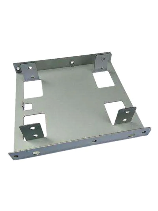
Two profiles at ninety degrees is a tolerance chain across two parts
This connector joins two profile ends at right angles, and the tolerance that matters is not the connector’s own dimensions but the relationship between the two legs after assembly. Hole pitch is called to ±0.10 mm and the right angle to ±0.5°, and each of those is individually comfortable. The combined effect is what decides whether the joint assembles.
The mechanism is straightforward once you see it. The connector’s two legs are perpendicular in the flat. When it is installed, one leg sits on one profile and the other on a second, and each leg locates independently. Any error in the connector’s angle is taken up as interference or gap at one of the two joints, not distributed.
- Right angle governs assembly, not appearance — a visually perfect connector at 0.4° out can stop a profile from sliding home. This is why the angle callout exists at all.
- Hole pitch relative to the leg — ±0.10 mm on pitch is only meaningful referenced to the leg face or edge, because that is what the mating profile sees.
- Both legs after one datum — dimensioning the second leg from the first, rather than both from a third feature, removes one degree of freedom from the chain.
- Form over individual dimensions — two holes can each be within tolerance and still miss their mating pattern by the accumulated error. The array span is the controlling dimension.
Hole pitch at ±0.10 mm across a span is an accumulated error
The pitch callout on this connector is the same kind of requirement as a stamped hole pattern anywhere else, and it behaves the same way. Each hole position is measured, each passes, and the pattern as a whole is out because the errors add up in one direction.
On a connector with holes along one leg, the pitch is usually set by the profile it attaches to, which is a different company’s extrusion. That has a specific consequence: the tolerance is not solely ours to hold. The mating profile has its own pitch tolerance, and the two add.
- Datum the pitch to the leg — pitch referenced to the profile-contacting face is measurable and controllable. Pitch referenced to a pierce datum edge picks up that edge’s own variation.
- Cumulative pitch callout — state the tolerance on the total span rather than per-hole, so that the error the assembly sees is what is controlled.
- Slotted hole where possible — one slotted hole per pattern absorbs the accumulated error between two different suppliers’ tolerances for almost no cost.
- Feed accuracy is the lever — on a 5–250 T press park the index pitch of the feed is usually the dominant term. Improving it costs less over a programme than the scrap from a drifting pattern.
The commercial question worth raising early is whether the mating profile is fixed. If it is, the connector’s pitch tolerance should be matched to the profile’s, not held to a tighter number that merely looks better on the drawing. A tighter pitch tolerance on our part does not make the joint assemble any better; it only makes our part harder to make.
Pre-galvanized steel at 1.5 mm is thin enough that forming order matters
At 1.5 mm pre-galvanized, this connector is in the range where the coating starts to participate in the forming rather than just sitting on the surface. The zinc-plus-conversion system is harder and more brittle than the steel underneath, and it will show its presence in three ways during forming.
First, cracking at the outside fibre of any bend. Second, a slightly different effective thickness than the nominal, because the coating adds to the sheet and its thickness varies across the coil. Third, a tendency for the coating to lift or flake where the bend radius is tight relative to the coating thickness, because the outer fibre stretches and the coating has nowhere to go.
- Effective thickness — a 1.5 mm pre-galv coil may measure 1.55–1.6 mm. Every bend calculation and flat pattern built on the nominal 1.5 mm will be slightly out, which is exactly enough to put a ±0.5° angle outside its band.
- Coating crack visibility — on a connector that ships bare, coating cracks at the bend are visible under magnification and will be reported as a quality issue even though the base steel is sound.
- Minimum radius — three to four times nominal thickness is a sensible floor on pre-galvanized material that will see any moisture exposure.
- Galvanized die surfaces — zinc on steel is a galling pair. Forming pre-galvanized material in a bare tool steel die can transfer coating onto the punch within a relatively short run, which then marks the part.
The last point is the one that catches people out on a family of parts. A die that runs clean on bare cold-rolled steel will not necessarily run clean on pre-galvanized, and the marking appears partway through a batch rather than from the first article. Specifying a suitable die surface treatment for pre-galvanized forming is cheaper than discovering the problem through marked parts.
The right angle is a forming tolerance, not a machined feature
±0.5° on a corner that joins two profiles is a springback tolerance, and on 1.5 mm pre-galvanized material the springback will move the finished angle by more than the tolerance band unless it is deliberately compensated.
The compensation method is the same one used everywhere else in stamping: measure the achieved angle at first article, calculate the offset, and set the tooling so the finished part lands on nominal. The offset goes into the die’s fabrication record so that a tool repair restores it.
- Two bends, two offsets — a connector forming two legs in one station will not necessarily spring back equally on both. Measure each leg separately.
- Sequencing — a leg formed after the other has already been formed sees a stiffer part and springs back differently. The order is a decision, not a default.
- Symmetry check — at first article, measure the angle at both legs on the same part. Left-to-right difference on a single part is a die alignment question; part-to-part difference is material.
- Angle versus squareness — on a connector the more useful measurement is the angle between the two leg faces, not the angle of each leg against the blank. That is what the assembly sees.
Where the connector has to hold two profiles at a defined angle in service rather than merely at assembly, add thermal and load consideration to the angle. A 90° joint in galvanized steel that is exposed to sun on one face will move, because the zinc and the steel have different thermal expansion behaviour and because a bolted joint will creep slightly.
Two failure modes a CMM report will not find
On a connector whose function is to join two profiles, the dimensional report and the functional failure are only loosely related, and it is worth being explicit about the gap.
The first failure is coating crack propagation at the bend root. The bend on this connector is a formed, work-hardened, coating-cracked region. Under cyclic loading in service, a coating crack in a pre-galvanized part is a initiation site, and the zinc layer does not heal itself.
The second is fretting at the fastener holes. A connector clamps two profiles with fasteners. If the pitch mismatch described earlier has to be absorbed somewhere, it is usually absorbed at the fastener itself, which then carries a small relative movement between two clamped surfaces.
- Burr side at the fastener hole — on 1.5 mm the burr stands roughly 0.04–0.08 mm. If the fastener clamps directly onto a pierced face, the burr becomes part of the clamping interface and the clamp load becomes position-dependent.
- Coating under the fastener head — where the fastener head bears on galvanized steel, the coating is crushed and can embed into the fastener, which then corrodes into the part. A washer or a specified coating exclusion changes this.
- Corner impact — a connector corner is the exposed part of an assembly and takes the first impact. On a thin-walled bent connector, an impact at the corner can open a bend crack that is invisible until it corrodes.
- Creep at the joint — a bolted galvanized joint under sustained load relaxes slightly over months. On a connector that must hold position, the preload specification matters more than the connector’s own dimensions.
The point for the drawing review is that all four of these are decided by geometry and specification, not by inspection. Bend radius, hole burr direction, coating exclusions under fastener heads and preload requirements are all free to specify on a drawing and expensive to change on a tool.
Why pre-galvanized and not zinc plated, and what it changes
This connector is supplied pre-galvanized rather than zinc plated, and although the corrosion protection looks similar, the manufacturing consequences are quite different.
Pre-galvanized material is coated at the mill, on the coil, before the part exists. Every downstream operation — punching, forming, trimming — happens on an already-coated surface, and each operation has to respect that coating.
- Forming sees coated material — with pre-galv, the punch and die must handle a coated surface, which raises the galling risk and constrains the minimum bend radius.
- Edges need protection after fabrication — the cut edges created by stamping interrupt the mill coating. That is why edge passivation is on the specification, and why sequencing it after the final operation matters.
- No dimensional consumption from plating — a plated part needs features punched undersize to allow for coating build. A pre-galvanized part has no plating step on the finished part, so hole and pitch tolerances are unaffected by any coating thickness. On a pitch-critical connector, that is a genuine advantage.
- Appearance consistency — mill galvanizing has a consistent spangle pattern across the part. Electroplating has a different appearance and a different colour consistency between lots.
On a part whose pitch tolerance is the dominant requirement, pre-galvanized is arguably the better process choice, because it removes plating thickness from the dimensional budget entirely. The trade is in forming: the coated surface is less forgiving and the bend radius requirement is tighter.
From die layout to repeat order on this connector
The connector runs as a progressive stamp on presses in the 5–250 T range with dedicated dies, first articles and batch samples checked on the CMM. The engineering content of the route is short but the sequence of decisions is not.
- Flat pattern and bend allowance first — with two bends and a 90° relationship between the legs, the flat pattern has to be derived from the bend allowance and the angle compensation before any piercing is laid out.
- Piercing on the flat — hole pitch is set while the material is flat and fully supported, which is the only condition under which ±0.10 mm on a pattern is comfortable.
- Forming last — the legs formed after the piercing means the pitch is set first and then the bend adds its allowance, so the compensation is applied once, deliberately, rather than inherited.
- First article against a finished reference — the signed sample should be a complete connector, not a flat blank. Repeat orders are gauged back to it.
On the commercial side, tooling for this connector is held under the part number, with maintenance tracked against the number, so a die can be re-cut from the original design data. Unusual walls, piercings or tolerances are feasibility-checked first rather than after quotation. Delivery is FOB Ningbo or Shanghai with T/T, L/C at sight or D/P.
The summary judgement on this part: the pitch and the right angle are both within normal process capability on 1.5 mm pre-galvanized material, and the real risks are elsewhere — coating cracking at the bends, edge corrosion if passivation is sequenced wrongly, and fretting at fasteners absorbing a pitch mismatch with the mating profile.
This part belongs to our Custom Metal Stamping Parts range. The custom metal stamping parts pages collect the process notes, common materials and inspection points behind every product in the family.
Specifications
| Item | Stamped Sheet Metal Frame Corner Connector |
|---|---|
| Brand | AUNOV |
| Designing | Built to the drawing you supply – unusual walls, piercings or tolerances are feasibility-checked first, and revisions are re-quoted once rather than silently absorbed. |
| Tooling | Tooling is held under your part number, which keeps tooling cost transparent, and maintenance is tracked against the part number. |
| Samples | First-article samples ship with a dimensional report and material certificate, and any deviation is corrected at sample stage, Production starts only after your written sign-off. |
| Materials | pre-galvanized steel, 1.5 mm; mill certificate and heat-number traceability supplied with the first article. |
| Surface finish | pre-galvanized; alternatives quoted against the drawing. |
| Processing | progressive stamp – a frame corner connector that joins two profile ends at right angles. |
| Equipment | Press shop with 5-250 T mechanical presses and dedicated dies; first articles and batch samples are checked on the CMM. |
| Tolerance | ±0.10 mm hole pitch; ±0.5° right angle; critical dimensions 100% gauged. |
| Delivery terms | FOB Ningbo or Shanghai; T/T, L/C at sight or D/P; repeat orders reuse the approved first article. |
Related Products
Request a Quote for This Part
Send a drawing or sketch — get material advice, tooling cost and a per-piece price within 24 hours (working days).