
Bend angle tolerance on galvanized steel is a coating question
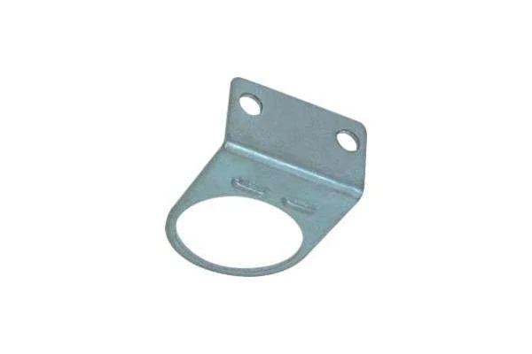
This angle bracket is formed in pre-galvanized steel at 2.0 mm, with the bend called to ±0.5°. That is a generous-looking figure which becomes much less generous once you account for what the coating is doing during the bend. Pre-galvanized material arrives with a zinc layer plus a conversion film, and both of those are brittle relative to the steel underneath.
The angle itself is a springback problem, and the coating is a cracking problem. They are separate, and conflating them is the usual reason a bracket like this comes back with a complaint that mentions rust weeks later rather than a complaint about the bend.
- Coating cracking at the outside radius — the outer fibre stretches in a bend. On 2.0 mm pre-galv, zinc coating around 8–12 µm plus conversion film will show visible cracking at a tight radius under magnification even where it looks acceptable by eye.
- Minimum bend radius — for coated material the practical minimum inside radius is set by coating adhesion, not by the steel. Roughly three to four times thickness is a reasonable floor for pre-galvanized material that will see any corrosion exposure.
- Edge protection — the sheared edge of pre-galvanized steel is where corrosion starts, because the coating is thin and the edge is exposed. This bracket is quoted with edges passivated for exactly that reason.
- Passivation timing — passivation after fabrication protects the freshly exposed cut edge. Passivated coil that is cut and never passivated will bleed rust from the sheared edges within weeks.
The honest framing for a customer is that a bend tolerance and a coating integrity requirement pull in opposite directions on radius. A tighter radius holds the angle more accurately in some geometries and cracks the coating more reliably. Where the bracket will be painted after fabrication, a wider radius and a sound coating matter more; where it ships bare, the radius should be generous.
Why this bracket is stamped and brake-formed rather than stamped alone
The process route here is press brake plus stamp, which is a deliberate choice and worth explaining, because a full progressive die could form the same geometry.
There is a cost consequence too. A progressive die that pierces and forms in one sequence needs stations for both, plus the strip feed and the tooling to hold the part during the bend. A stamp for the pierce and circle is a simple two- or three-station die. A brake setup is a tool cost that can often be shared across several bracket families.
- Pierce in a flat, supported condition — hole position at ±0.10 mm is far easier to hold while the blank is flat than while it is part-formed.
- Bend length independent of pierce — on the brake the bend length is set by how far the operator positions the part, which is a setup variable rather than a die variable.
- Springback compensation is easier — the over-bend amount can be dialled in on the tooling at the brake without touching a die insert.
- The trade — you lose the guaranteed relationship between the hole and the bend that a single die would give you, and you gain flexibility. Which side of that trade matters depends entirely on how tight the hole-to-bend relationship needs to be.
There is a datum consequence that should be settled before production. On the two-operation route, the brake operation has to locate the part on something. The obvious choice is the pierced hole, using a dowel or a pin.
A hole pierced before bending moves when the bend happens
This is the specific reason the two-operation route carries a risk that the single-die route does not, and it is worth stating plainly. A hole is pierced while the bracket is flat. Then the bracket is bent. The bend consumes material: the neutral axis shortens on the inside of the bend and the flange grows. Any hole in the flange region moves with that material.
So the hole-to-bend relationship on this bracket is only as stable as the hole’s distance from the bend line. A hole 10 mm from the bend line on 2.0 mm material will shift measurably when the flange forms; a hole 40 mm away will shift far less.
- Bend deduction — on 2.0 mm steel with a 6 mm inside radius at 90°, bend deduction is roughly 1.2–1.5 mm and bend allowance roughly 2.6–2.9 mm. Every dimension taken from the bend line moves by that amount.
- Springback — springback opens the angle slightly, which increases the effective flange length and shifts holes in the flange outward. This is the same effect that makes the ±0.5° angle tolerance meaningful.
- Hole ovality from the bend — a hole close to the bend line distorts into an oval because the material around it flows differently on each side. Beyond about three times thickness from the bend line this stops being significant.
- Measure after, not before — the sample that gets signed should be a finished part, bend and all. A signed pre-bend sample is not a valid reference for a post-bend inspection.
Where the hole position relative to the bend is genuinely critical — say the bracket has to bolt flush against a face — the correct fix is not to argue for a tighter brake tolerance but to change the design: either move the hole further from the bend, or make the bend the datum and dimension the hole from it after the bend, in the flat pattern coordinates that actually reflect the finished part.
The ±0.5° callout is a springback number, not a brake accuracy number
Press brakes are more accurate than ±0.5°. Repeatability on a modern CNC brake with good tooling is comfortably better than that. So where does the tolerance actually come from, and why does a bracket with the same nominal angle still vary from part to part?
Springback. The material elastically recovers when the tooling releases it, and the amount of recovery depends on the grade, the thickness, the bend radius and the bend length. On 2.0 mm pre-galvanized steel the recovery is consistent enough to compensate for, and the compensation is simply over-bending by a measured amount at first article.
- Over-bend compensation — measure the achieved angle at first article, compute the offset, and set the tooling to the compensated condition. Record it so a tool repair restores it.
- Grain direction — bending transverse to the grain direction generally produces more springback than bending along it. Specify the orientation on the flat pattern.
- Bend length effect — longer bends spring back slightly differently from short ones because of the tooling’s own deflection along the length.
- Coating thickness effect — the zinc layer is softer than the steel and adds a small amount to the effective thickness, which shifts the bend calculation by a small amount. Small, but not zero at ±0.5°.
The practical consequence is that if angle variation appears mid-batch, the material is the first thing to check, not the brake. A coil at the top of its specified yield range springs back more than one at the bottom. That shows up as a gradual drift across the batch rather than a step change, and it is the signature that distinguishes a material problem from a setup problem.
Pre-galvanized edges and the corrosion clock
This bracket is finished pre-galvanized with edges passivated, and that combination is doing two separate jobs that are often confused. The galvanizing protects the steel. The edge passivation protects the cut edge specifically, where the galvanizing layer was interrupted by shearing and the protection is weakest.
The failure sequence on an unpassivated cut bracket is predictable and fast. Shearing interrupts the zinc layer and exposes steel at the edge. The exposed steel is cathodically protected by the surrounding zinc for a while, which delays visible rust.
- Shear face quality — a torn shear edge from a dull punch exposes more area and larger crystals than a clean sheared one, and rusts faster. Punch condition is a corrosion control, not only a burr control.
- Edge break — a 0.1–0.2 mm break on the cut edge dramatically improves coverage, because the coating can bridge a rounded edge far more effectively than a sharp one.
- Passivation chemistry — the passivation film has to be formed after the edge is exposed. Passivating the coil and then cutting is not the same as passivating the part, and the second is the one that helps.
- Coating thickness at the bend — the bend itself creates fresh surface at the outside fibre, so the bend area needs the same protection consideration as the cut edge, especially if the bracket ships bare.
One practical point on the two-operation route. The stamping operation creates the cut edges; the brake operation then creates new surfaces at the bend. If passivation follows both, the part is properly protected. If it happens after stamping only, the bend is unprotected.
Whether the circle belongs in the stamp or on the brake
The circular cutout on this bracket is pierced in the stamping operation rather than cut on the brake, and that is the right call for a few reasons that are worth stating because it is not always obvious.
A circle pierced in a die is a clean sheared hole with a controlled burr and a repeatable position relative to the bend line. The same circle cut on a brake puncher is perfectly serviceable for low volume but has no repeatable relationship to anything except the operator’s setup, and its position relative to the bend depends on the setup rather than on the tool.
- Position to the bend — pierced in the flat blank with the bend line referenced, the circle position is set by the die and holds to the pierce tolerance. Cut on the brake, it is set by where the part is placed.
- Hole quality — a die-pierced circle has a controlled burr height and a clean shear edge, both of which matter more on a galvanized part than on bare steel because the coating has to bridge the edge.
- Tooling cost — adding a pierce to an existing stamp is cheap. Adding a puncher tool to the brake setup for one feature is a comparable cost with none of the positional benefit.
- Where the circle goes if it is on the brake — if the volume is low and the circle is purely decorative, a brake puncher is defensible. If it locates anything, it belongs in the die.
The engineering question behind all of this is whether the circular cutout is functional. On a bracket like this it is often a cable pass-through, a fixing for a trim panel, or a clearance for a mating boss. If it is any of those, its position is functional and it belongs in the die with a stated tolerance.
Quoting this bracket: what changes the price and what does not
On this angle bracket, the cost drivers are knowable and the tolerance drivers are separate from them, which is a useful thing to establish before the quotation rather than after.
- Material — pre-galvanized steel at 2.0 mm with mill certificate and heat-number traceability. The coating spec matters more here than the steel grade, because the forming route depends on the coating behaviour.
- Route — stamp plus press brake, with in-die sensing available on the press park. The two-operation route is quoted as such, and it is cheaper than a full progressive at this volume.
- Bend tooling — brake tooling is often the reusable element across a family of brackets. Where the customer has several similar angles, sharing the tooling setup is a real saving worth asking about.
- Passivation and edge protection — specified, sequenced after the final operation, and included in the inspection scope.
What does not change the price: holding ±0.10 mm hole position and ±0.5° bend, provided the hole is pierced in the flat and the bend is compensated. Those are normal process capabilities on this material and thickness.
Delivery here is FOB Ningbo or Shanghai with T/T, L/C at sight or D/P, and repeat orders are gauged back to the approved first article. That reference should be a finished, passivated part.
Custom Metal Stamping Parts is the range this part sits under; the overview page pulls together the tooling logic, finishing options and tolerance notes that apply across the family.
Specifications
| Item | Galvanized Stamped Angle Bracket with Circular Cutout |
|---|---|
| Brand | AUNOV |
| Designing | Made to your 2D/3D drawings (PDF, DWG, STEP, IGS) – DFM notes come back with the quotation, so changes are priced before tooling is cut. |
| Tooling | Die, fixture and gauge work stays in our own toolroom, which keeps tooling cost transparent, and lead time is measured from tooling start. |
| Samples | Samples are issued for approval before the run, and any deviation is corrected at sample stage, Later batches are gauged back to the signed sample. |
| Materials | pre-galvanized steel, 2.0 mm; mill certificate and heat-number traceability supplied with the first article. |
| Surface finish | pre-galvanized, edges passivated; alternatives quoted against the drawing. |
| Processing | press brake + stamp – a galvanized angle bracket with a circular cutout. |
| Equipment | Press park 5-500 T (mechanical 5-250 T, hydraulic 250-500 T) with in-die sensing, press brake cells and an on-site toolroom. |
| Tolerance | ±0.10 mm hole position; ±0.5° bend; critical dimensions 100% gauged. |
| Delivery terms | FOB Ningbo or Shanghai; T/T, L/C at sight or D/P; repeat orders reuse the approved first article. |
Related Products
Request a Quote for This Part
Send a drawing or sketch — get material advice, tooling cost and a per-piece price within 24 hours (working days).