
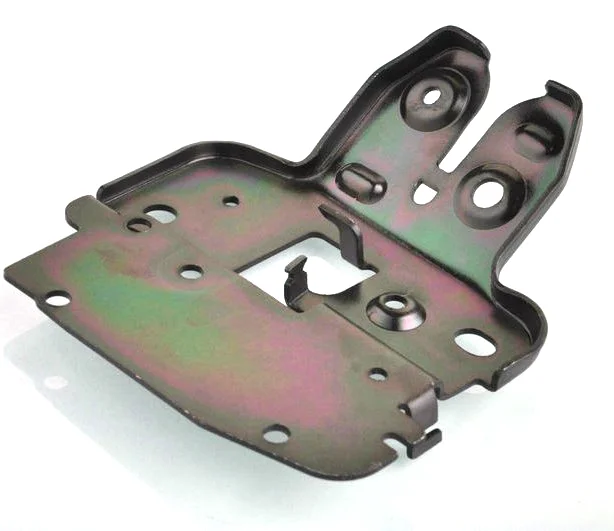
A ±0.10 mm slot position is a harder measurement than a round hole
Round holes are circles with an unambiguous centre however the burr breaks them. A slot has two ends and two radii, and the tolerance you actually need sits on the slot’s own centreline rather than on either end radius. Those numbers differ, and on a long slot the difference is substantial. On a 24 mm slot at ±0.10 mm, the end radii can each sit inside their own tolerance while the centreline has shifted by most of the band, because the slot has stretched: during piercing the ends are pushed apart by the clearance allowance plus the burr contribution, and the strip is still under tension across the cut when the length settles.
This plate carries both slotted and round piercings, which is the useful part: the round holes establish the datum, the slots define the adjustment envelope. The practical discipline is to dimension slots centre-to-centre against the round hole, not each slot end to a corner — one change that turns an unmeasurable requirement into a CMM programme anyone can run.
- Slot stretch budget — set the die opening undersize by the measured stretch, typically 0.01–0.03 mm on the length for 2.0 mm HSLA. Empirical from first article, not a catalogue value.
- Datum choice — put the datum on a round hole or the pierce datum edge, never on a slot, which inherits its stretch and burr asymmetry.
- Tap width — a narrower punch needs more force for the same pierce and deflects more. On a 2.0 mm HSLA plate, 6 mm slot width against a 10 mm round hole means the slot punch is the weaker of the two and the one that will drift first.
- Lead-in radius — the radius at each slot end is where burr breaks away; a generous punch end radius reduces the risk of a corner crack appearing mid-run.
The ±0.5° corner angle callout hides the real error term
Corner angles here are called out at ±0.5°, which looks generous until converted. At a 45 mm corner leg, half a degree of swing moves the leg tip roughly 0.4 mm — the same order as the flange tolerance on the same part, and the two errors are not independent, since they share a common cause in the shut-off.
To a customer who wants the corner angle tightened, the key point is that the angle is not governed by the accuracy of a machined corner on the punch. It is governed by how consistently material flows into the corner at the moment of forming. A corner that fills unevenly sits at a different angle on the left of the plate than the right, in the same stroke, and no amount of die machining fixes that. The variables that matter are corner relief, yield point variation across the coil, and whether the corner forms in one station or progressively.
A sharp 90° corner with no relief stretches the outer fibre, and on 2.0 mm HSLA with a high yield point that crack often does not appear until the part is painted and thermally cycled. It then propagates at the corner rather than at the pierced holes, and gets attributed to material rather than forming. The preventive measure is corner relief designed at flat-pattern stage — a drawing-review item that costs nothing to add.
What we hold reliably is left-to-right symmetry on a single part, which is a die alignment question. Part-to-part variation is a material and lubrication question, and it responds to incoming coil control more than to anything in the toolroom.
Springback in 2.0 mm HSLA is large enough to change your flat pattern
HSLA at 2.0 mm has a yield strength high enough that springback is a first-order effect, not a correction. On a simple 90° bend the elastic recovery can exceed a degree and a half depending on grade and bend radius. Develop the flat pattern on an assumed radius and then form over a different effective radius — because the punch has been polished or worn — and the finished angle sits outside ±0.5° with no manufacturing fault to point at.
This is handled by over-bending to a target rather than bending to the drawing angle. At first article we measure the achieved angle, calculate the springback offset from bend radius and grade, and set the punch shut-off so the finished part lands on nominal. The offset goes into the die’s fabrication record, so that when the punch is repaired whoever re-machines it restores the compensated condition, not the theoretical one — the most commonly lost piece of information in a stamping programme.
- Radius choice — a larger inside radius reduces springback but increases the bend allowance and therefore consumes more flat width. On this plate there is usually room; on a tight bracket there may not be.
- Material grade consistency — springback scales with yield strength, so a coil at the top of its specified yield range springs back more than one at the bottom. A plate that drifts out of angle across a batch often has a material story behind it.
- Stiffening effect — if the corner is formed after adjacent flanges, the neighbouring flange stiffens the corner region and reduces its springback. Operation order therefore changes the angle, not just the flat.
- Grain direction — bend allowance differs measurably between longitudinal and transverse forming on HSLA. Specify grain direction on the flat pattern, or accept a few degrees of angle wander.
Deburring a slotted plate without eating the slot position
Deburring is priced as a simple operation and is where much of the dimensional argument is lost. Vibratory or tumble deburr rounds the hole and slot edges, which is intended — but the same operation rounds the entry lip, and after rounding the edge the CMM is supposed to measure no longer exists as a sharp feature. The gauge report then disagrees with itself run to run, depending on which part of the rounded edge the probe finds.
For round holes this is manageable, because a rounded hole still has a centre. For slots it is worse: rounding the two ends shortens the effective centreline slightly and rounding the long edges changes the width. On a 6 mm wide slot with a 0.1 mm edge break the width reads 0.2 mm smaller than the pierce produced. Not a defect, but if the drawing calls ±0.05 mm on slot width and the deburr is uncontrolled, a systematic offset is now built into the inspection.
The clean solution is to specify which features the deburr may touch. Masked deburring on functional slots — mask applied before tumbling — costs a little labour and saves the argument entirely. It is worth doing on any slot carrying a fastener or locating function, and not worth doing on slots that will be painted over anyway.
- Burr side — burr height on 2.0 mm HSLA typically runs 0.04–0.10 mm. If a slot carries a fastener head, the burr needs to be on the far side from the bearing face.
- Media selection — coarser media cuts faster and leaves a larger edge break; finer media is gentler and slower. Match media to the edge break the drawing tolerates, not to throughput targets.
- Part-to-part masking yield — masking is the main cost. On a plate with six or more functional slots, in-line masking before deburr amortises better than hand masking after.
- Post-deburr inspection — gauge after deburr, not before, and make the signed sample a post-deburr part so the reference reflects what ships.
Flatness on a seat plate is a residual-stress problem wearing a tolerance
Nothing on this drawing calls out flatness, and on a seat mounting plate that is often deliberate — the plate is bolted to a frame and is not expected to lie flat. It is worth thinking about anyway because the mechanism that bows the plate also moves the slot positions, and it varies across the batch.
Piercing releases the compressive stress locked into coiled strip. Once cut free, the plate redistributes it, and because the pierce pattern is not symmetric the redistribution is not symmetric either — the plate takes a slight twist. The effect is small in absolute terms, a fraction of a millimetre over 300 mm, but enough to shift a far-field slot against the datum by a meaningful fraction of ±0.10 mm.
Forming leaves residual stress around formed features. Where flanges are formed on one side only the plate is asymmetric through its thickness, and some of that survives cutting — which is why flatness tends to worsen as forming stations are added, not improve.
What helps: minimise forming on the plate where the design allows, so flanges are symmetric or consolidated into one operation; keep the pierce pattern balanced about the plate centre; and control coil tension at the decoiler, since excessive tension during piercing pulls the strip and adds to the redistribution. All are design and setup decisions made at quotation stage rather than retrofitted after complaints.
Zinc, nickel, e-coat or anodise changes the tolerance budget
The finish here is not cosmetic on 2.0 mm sheet — plating thickness consumes dimensional budget directly. A zinc electroplate at 8–12 µm adds that much per surface; on a 6 mm slot that is 16–24 µm of width, a quarter of a typical ±0.05 mm slot width tolerance, before build on the radiused ends. Nickel is thicker still and forces a deliberate punch undersize.
This is a solvable problem, but it has to be solved at design stage rather than discovered at the plating line. The standard approach is to dimension the punched part to suit the finished, plated condition, and to tell the plater which surfaces are functional and which are sacrificial. Masking the functional surfaces preserves their tolerance and costs less than plating-then-rejecting.
- Zinc — blue-white and iridescent chromate conversions are standard for this plate class. Both are thin; the dimensional cost is at the low end and the fit tolerances can generally be held.
- Nickel — materially thicker than zinc. Expect to undersize slots and holes by the nominal plating thickness, and confirm whether the customer’s mating part is plated or bare before fixing the target.
- E-coat — a paint film rather than a metal plate. Dimensional cost is small, but the coating is an electrical insulator, so any grounding path through the plate must be specified and masked.
- Passivation — effectively zero dimensional cost, and the cheapest answer where the only finish requirement is appearance plus salt-spray resistance.
Salt-spray performance is the other finish conversation worth having early. It is set by coating thickness and edge protection, and on a punched, deburred part the edges are where corrosion starts. A plate with a 0.05 mm plated edge break outlasts the same plate with a sharp break at identical nominal thickness, for reasons unrelated to coating chemistry.
Running this plate on a 5–250 T press without wasting a stroke budget
This plate runs as a progressive stamp with slotted and round piercings on mechanical presses in the 5–250 T range. The decisions that follow are about how many stations it genuinely needs and how the tonnage is spent across them.
We plan the operation count with the press already chosen, because a 40 % tonnage increase is a real price difference at this volume.
- Pierce first — piercing while the blank is flat and fully supported gives the tightest positions. Move piercing later only when a late pierce materially improves the pattern.
- Combine forms — two shallow flanges formed in one station need less tonnage than two stations, provided the undercut does not create a forming interference. This is the main lever on press size.
- Plan relief, not interference — where a 0.5° corner and a flange meet, use relief in the punch rather than a two-stage form. Relief costs a little accuracy and saves an entire station.
- Trim in the last station — cutting the profile free last keeps the part attached while formed, controlling springback and twist better than cutting early.
The secondary operations available for this part should be quoted as a route decision rather than a fallback. Any feature movable to a CNC turning centre as a separate op often comes out of the die cost entirely, at the price of an extra handling and a second datum. For a feature that is neither load-bearing nor dimensionally critical to the assembly, that trade is usually worth making — and worth asking about at quotation stage rather than discovering the die has grown by two stations and a week.
This part belongs to our Custom Metal Stamping Parts range. The custom metal stamping parts pages collect the process notes, common materials and inspection points behind every product in the family.
Specifications
| Item | Automotive Seat Stamped Mounting Plate |
|---|---|
| Brand | AUNOV |
| Designing | Made to your 2D/3D drawings (PDF, DWG, STEP, IGS) – the die is planned around your critical features, and revisions are re-quoted once rather than silently absorbed. |
| Tooling | Die, fixture and gauge work stays in our own toolroom, which keeps tooling cost transparent, and lead time is measured from tooling start. |
| Samples | Pre-production samples come with a full inspection report, so the seat stamped mounting plate is proven before volume production, The signed sample is retained for future reorders. |
| Materials | HSLA steel, 2.0 mm; mill certificate and heat-number traceability supplied with the first article. |
| Surface finish | Zinc, nickel or chrome plating, anodising, passivation or e-coat; masking and laser marking available where needed. |
| Processing | progressive stamp – a seat mounting plate with slotted and round piercings. |
| Equipment | Press shop with 5-250 T mechanical presses and dedicated dies; secondary ops run on CNC turning centres, inspection on the CMM. |
| Tolerance | ±0.10 mm slot position; ±0.5° corner angles; critical dimensions 100% gauged. |
| Delivery terms | FOB as standard, with DDP offered for EU and US addresses; T/T or L/C, sea or air freight quoted to your door. |
Related Products
Request a Quote for This Part
Send a drawing or sketch — get material advice, tooling cost and a per-piece price within 24 hours (working days).