
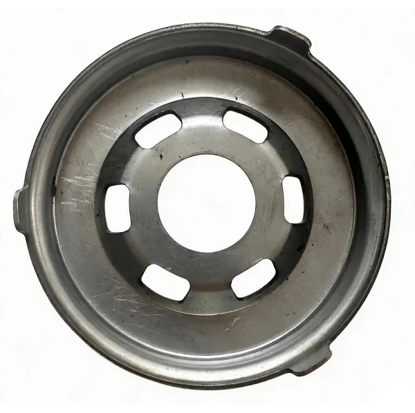
One stroke from flat disc to end cap, with everything that implies
A circular motor end cap drawn deep in a single press stroke is a demanding part, and the difficulty is not the depth – it is that every dimension on the finished cap is downstream of one irreversible event. Once the blank has been pulled into the die, wall thickness at the base of the wall, flange diameter, roundness of the bore area and the position of the bolt circle are all consequences of how much material was allowed to feed into the draw and how much friction it met on the way. None of them can be corrected afterwards by careful measurement. The only place to influence them is in the design of the tool and in the specification of the incoming material.
We draw these in 1.8 mm cold-rolled steel, holding the bore to +/-0.05 mm and the bolt circle to +/-0.10 mm with critical dimensions 100% gauged, on 5-250 T mechanical presses with progressive dies and CNC turning centres for secondary operations, verified on a CMM. What follows is about what decides whether a deep drawn cap is repeatable, written for the engineer who has to put tolerances on the drawing and mean them.
Draw ratio and blank diameter are set before the press opens
The first number that decides everything is the ratio of blank diameter to cup diameter at the start of the draw. For a cup drawn to height h from a blank of diameter D0 with final diameter D, the conventional limit for a first draw in low-carbon steel is a total area ratio around 0.70 to 0.75. Past that, the flange has to feed material inward faster than the draw pulls it in, the flange wrinkles, and the wall stretches beyond what the material tolerates.
For the drawing, the consequence is that blank diameter should be a controlled dimension rather than a supplier’s choice. A supplier allowed to substitute a blank within a generous band will deliver a cap at the correct height with a different flange width every time, and the bolt circle – frequently located from the flange edge – moves with it.
Wall thinning lives at the corner and nowhere else
As material flows around the punch nose radius it is bent around that radius and straightened again, and the outer fibre travels further than the inner. The result is local thinning at the base of the wall, and the thinning is a function of the ratio of punch nose radius to thickness. The conventional guideline is a nose radius of at least 4 to 5 times material thickness; on 1.8 mm that means 7 to 9 mm. Below about 3 times thickness, thinning at the corner becomes a controlling dimension on the part even though the corner is nowhere near a functional feature.
The consequence that surprises people: the minimum wall on a deep drawn cap is almost always at the corner, and it is not the wall anyone dimensioned. A drawing stating “1.8 mm wall” and nothing else has specified a nominal for a region where the actual material is 1.6 mm, and will be 1.5 mm at the low end of the thickness band. If the wall carries pressure, a stiffness requirement or a corrosion allowance, the minimum wall has to be stated as a minimum, at the corner, with its location identified.
Blank holder force is the entire control loop
Material feeding into the draw has to pass under the blank holder, and the friction that holder generates is what makes the draw stable. Too little force and the flange wrinkles; too much and material cannot feed, the wall stretches more, thickness drops faster, and the draw force climbs until something tears.
- Wrinkling appears at the flange in a four-lobed pattern matching earing. It looks like earing and is frequently misdiagnosed. The distinguishing feature is that earing scales with blank size while wrinkling scales with holder force. If the lobes grow when the blank diameter grows, it is earing; if they appear at constant blank with force adjusted, it is wrinkling.
- Tearing appears at the corner, starting at the punch nose radius and running circumferentially. It is a length-thickness failure and is not visible from outside until significant.
- Between the two limits is a window, and on a high-volume cap that window decides whether the tool is viable. It narrows with increasing thickness, with higher-strength material and with depth. HSLA at the same thickness has a narrower window than mild steel because its forming limit sits closer to its yield.
- In-die sensing plus a monitored force window is what makes it repeatable. A press that reports tonnage against a defined curve detects a wear condition, a material change or a misfeed without pulling a part apart to find out.
The bore at +/-0.05 mm is machined, and that is a two-operation tolerance
The bearing bore on this cap is held to +/-0.05 mm, and that is achievable because the bore is machined after drawing – not because the draw can produce it. This distinction has to be explicit on the drawing, because it determines both the tolerance and the datum.
The chain that must hold together is: the as-drawn blank becomes machining stock, the fixture locates the cap by a feature that exists before machining, and the bore is cut relative to that fixture. For the result to be repeatable the fixture must locate on something stable.
- The flange rim is a poor locating feature. It is where the earing is, where draw-in variation shows, and it is flexible. A cap located on its flange will have its bore wander by the earing amplitude – a few tenths of a millimetre, ten times the bore tolerance.
- The outer cylindrical wall is better but not good. Round and fairly stiff, but it carries the draw’s own ovality and the local thickening at the corner. A fixture that grips the outside wall and expands into it will find the roundest section, which may not be the section the bore is cut from.
- A machined register is the right answer. The standard construction is to machine a locating step or spigot before the bore is cut, then locate the whole machining operation on that. The spigot is machined from the same setup as the bore, so the bore-to-register relationship is held directly, and the register itself is cut from material whose position is defined by the outer wall.
This is why a tight bore tolerance on a drawn cap is a two-operation tolerance rather than a one-operation tolerance. If the print asks for a machined register and does not exist, the fixture designer has to invent one from whatever is on the cap, and the result is a tolerance met on the sample and missed on the four-hundredth part when the fixture wears.
The bolt circle at +/-0.10 mm sits in a similar position. Holes pierced in the flat blank before drawing have their angular position set by the punch and their radius grown by the draw. Holes pierced after drawing are set by the fixture and inherit everything the fixture does. Piercing before drawing is normally better for angular position and worse for radial position, since radial distance depends on draw ratio; piercing after drawing is better radially if the fixture is good. Which is right depends on whether the bolt circle is referenced to the flange edge or to the bore, and that has to be decided on the drawing.
Coating a drawn steel cap, and the fits the film closes up
The finish here is selected from the drawing – plating, coating, anodising or passivation – and the choice is not neutral, because a drawn steel cap has several features toleranced tighter than a 60 to 90 micron coating.
- The bore. A build-up of 60 to 90 microns on a bore at the low end of tolerance reduces diameter by 0.12 to 0.18 mm. If the bearing bore has a defined fit, the coating must be masked there or the fit specified on the coated part. Masking is cleaner.
- The register or spigot, same problem with worse consequence, because the register is what holds the cap in axial position. A plated register will not seat fully and the assembly will appear to have end play.
- The seating face. Coating on a face meant to be flat closes against a housing rim and can open a gap at the outer edge of the joint.
- Bolt holes. Plating reduces hole diameter. Harmless on a clearance hole; on a tapped hole it is a thread-fit change, and the coating has to be masked or the thread specified as plated.
So the masking list here is not a formality – it is the list of features whose tolerances are tighter than the coating thickness. Finish thickness should be stated as a range with a measurement method rather than as “as required”, and adhesion is checked on the first article.
Questions worth asking on a deep drawn motor end cap
These are the questions where the answer changes the tool or changes the acceptance method, which is why they belong in writing before the die is designed.
- What is the draw ratio for this blank and cup, and is the part on the drawing side or the stretch-forming side of the limit?
- Is the blank diameter a controlled dimension, and is blank orientation marked so earing is repeatable?
- What is the punch nose radius, and is it at least 4 to 5 times material thickness?
- Is the minimum wall stated, at the corner, accounting for the low end of the thickness band?
- Is blank holder force monitored in-die, with a defined force window for the run?
- Is the bore machined, and is there a machined register so the bore-to-register relationship is held directly?
- Are bolt holes pierced before or after drawing, and is the bolt circle referenced to the flange edge or to the bore?
- Is the register masked for coating, and is coating thickness stated as a range with a method?
- Is wall thickness measured on a sectioned first article, at the corner rather than at mid-wall?
- Is the signed sample retained as the reference for later batches?
If the answer to the first question is that the part sits close to the draw limit, the other nine matter less than finding out whether a slightly shallower cap or a slightly larger blank is acceptable, because that one decision is worth more than every measurement decision that follows it.
This part belongs to our Custom Metal Stamping Parts range. The custom metal stamping parts pages collect the process notes, common materials and inspection points behind every product in the family.
Specifications
| Item | Deep Drawn Circular Motor End Cap Stamping |
|---|---|
| Brand | AUNOV |
| Designing | Built to the drawing you supply – unusual walls, piercings or tolerances are feasibility-checked first, and the approved print governs every later batch. |
| Tooling | Progressive and single-stage dies are designed and built in house, so a die can be re-cut from the original design data, with ownership confirmed on the quotation. |
| Samples | Samples are issued for approval before the run, so the deep drawn motor end cap is proven before volume production, The signed sample is retained for future reorders. |
| Materials | cold-rolled steel, 1.8 mm; mill certificate and heat-number traceability supplied with the first article. |
| Surface finish | Finish selected from the drawing: plating, coating, anodising or passivation; finish thickness and adhesion checked on the first article. |
| Processing | deep draw – a circular end cap drawn deep in one press stroke. |
| Equipment | Mechanical presses 5-250 T with progressive dies, with CNC turning centres for secondary operations and CMM inspection. |
| Tolerance | ±0.05 mm bore; ±0.10 mm bolt circle; critical dimensions 100% gauged. |
| Delivery terms | Shipping terms are set with the order: FOB, CIF or DDP, T/T or L/C, door delivery quoted. |
Related Products
Request a Quote for This Part
Send a drawing or sketch — get material advice, tooling cost and a per-piece price within 24 hours (working days).