
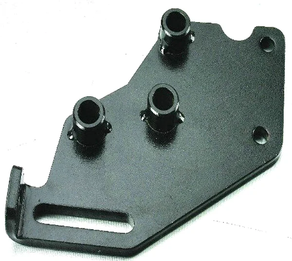
A bracket with locating bosses and a keyed slot is an assembly component, not a stamped shape. The holes and the outline are easy; the bosses and the key are what make the part do its job, and they are where the drawing usually leaves the most room for interpretation.
The function of each feature is distinct, and each one implies a different tolerance strategy. Treating them all as “stamped features” is how a bracket arrives that fits loosely in one axis and not at all in another.
Locating bosses: which axis actually locates
A locating boss is a raised cylindrical feature that enters a hole to establish position. The useful thing about a boss is that it converts a position requirement from a hole tolerance into a boss tolerance, and that changes what is achievable.
Three arrangements are common, and the engineering decision is which one locates and which one merely guides.
- One shoulder boss on a face, plus holes. The shoulder takes the axial load and establishes the plane; the holes establish the other two axes. This is the most robust arrangement and the one to use where axial repeatability matters.
- Two pins in the same hole. Common and cheap, and it locates in two axes while the part can rotate. A slot in the mating part can be used to prevent rotation where it matters.
- A dowel pin and a screw. The dowel carries the shear load and sets position; the screw clamps. This is correct where the joint must resist force without relying on friction, and it is the arrangement that does not loosen.
On a drawing this means stating which features locate and which clamp. Without that, a bracket may be assembled with two features fighting each other, and the result is a joint that is preloaded in the wrong direction.
Boss diameter tolerance and why it is not the same as the hole tolerance
A boss that enters a hole has to be toleranced against that hole, and the pair behaves differently depending on whether the fit is clearance, transition or interference.
- Clearance fit. The boss is smaller than the hole. The part locates but it can move, and it will move in service. Correct where the joint needs to be assembled without force and where the movement does not affect the function.
- Transition fit. The sizes are close and the joint locates well but may be assembled with light force. The usual answer for a locating boss.
- Interference fit. The boss is larger than the hole and the joint locates very well but has to be pressed or driven. On a thin stamped bracket an interference fit is often impossible because the surrounding sheet distorts instead of expanding.
The important detail is the tolerance on the boss height as well as its diameter. A boss that is 0.15mm too tall will pull the mating part off its seating face, and that error appears as a problem with the joint, not with the boss.
A second detail that is frequently omitted: a boss with a hole through it, or a boss that is part of the stamping, will have a burr or a thinning at its base on the side the material flowed from. If the boss enters a hole, that burr becomes an interference and the part does not enter. Where the boss is rolled or formed rather than stamped, the surface is work-hardened and may gall in service.
The keyed slot: preventing rotation with a deliberate fit
A key slot is a slot shaped so that a mating key or tab can only enter in one rotational position. Its purpose is assembly error prevention, and it is one of the cheapest ways to make a part foolproof.
The design question is the fit in the rotational direction.
- A straight slot. A key in a straight slot can rotate freely along the slot. It prevents nothing unless the slot is exactly the key width. This is the commonest failure: a slot drawn as a rectangle, intending to prevent rotation, providing none.
- A slot with a narrowed end, or with side flats. This is what actually keys. The narrowed section gives angular clearance, and the amount of that clearance is a real dimension that has to be stated.
- A closed slot with a lead-in. A lead-in chamfer makes the part easy to assemble and does not affect the keying function, but it has to be large enough to be useful.
The angular clearance in the key is the functional tolerance, and it should be specified as an angle or as the width difference that produces it. It is also affected by the burr from piercing — a slot pierced from one side has a burr on the other, and a burr in the keying direction will prevent the part from entering at all.
The second thing about a key slot is that it defines an assembly direction. A slot that can only be entered from one side means the bracket has an orientation, and everything else on the drawing should be consistent with it.
Multi-hole patterns and the datum that makes them repeatable
A bracket with many holes is either dimensioned from its edges or from a datum pattern, and the choice determines whether the holes can actually be inspected.
- True position from a datum frame. The correct approach. Holes are toleranced in position relative to the datums, so the pattern can be verified on a CMM and it can be interchangeable with its mate.
- Dimensioned from edges. Acceptable where the edges themselves are cut in the same tool, because then the relationship between edge and hole is fixed by the tool and does not vary. It is a legitimate approach and it is much cheaper to inspect with a plate gauge.
What is not acceptable is a mixed scheme where some holes are toleranced from the edge and others from each other, because the tolerance stack then runs in an unpredictable direction.
Where a pattern must be repeatable across batches, the hole pattern itself should be called out as the controlling feature and the outline should be toleranced to it — because the outline is easier to change without affecting function.
Burr direction is a functional requirement on a multi-hole bracket
Every hole has a side it was pierced from, and on this type of part that side matters more than the burr height.
- Facing holes. A counterbore or a countersink gives a flat seat for a fastener head. The burr should be on the opposite side from the seat, and this is a requirement about hole orientation that a burr height tolerance does not express.
- Boss holes. A hole through a boss needs the burr removed or oriented so the mating part can enter.
- Key slot. The burr must not be in the entry direction or the assembly will not go together.
- Fastener holes in a coated part. If the coating is applied before assembly, the hole edge will chip during assembly and this is where the coating failure that eventually leads to rust starts.
The drawing should state the burr orientation for the controlled holes, which is normally expressed as a note tied to a symbol on the relevant dimension.
Stiffness on a bracket with thin webs
A bracket is a structural part and the section between a mounting hole and a load point is the whole design. On a 2.5mm bracket with a pattern of holes, the stiffness is entirely in what is left between them.
- Web width between holes. A narrow web will flex under load and the part will lose position. The minimum web between a hole edge and a bend is a real design dimension.
- Bend relief. Where a bend line meets a hole or a notch, the sharp transition is a stress concentration and it will crack at the bend. A relief notch with a defined radius is needed, and the radius matters more than the depth.
- Material in the load path. The section through the bracket’s mounting face needs enough thickness to carry the bolt load without deforming, and bolt hole elongation on a thin bracket is a real failure mode.
On a bracket that sees a dynamic load, the stress concentration at the hole edge and at the bend relief is what limits the fatigue life, and it is set by geometry rather than by material. Round the hole edge, provide a generous bend relief radius, and avoid a sharp notch.
Coating on a bracket: the hole edges are the weak point
A protective coating on a steel bracket is straightforward in principle and awkward in the details, because the coating is applied before assembly and the assembly damages it exactly where it matters.
- Mask the bearing surfaces if the bracket is a current-carrying or grounding connection.
- Mask the hole edges where a fastener will seat, so the fastener bears on metal rather than on coating.
- Coating inside the boss bore will change the fit, and on a close-tolerance boss it can prevent assembly. Masking the bore is often necessary.
- Repair of damage. On a functional bracket, a damaged coating on a visible area is a cosmetic issue; on a hidden area it is a corrosion issue. It is worth stating whether touch-up is required.
Questions worth asking on a bracket with locating features
- Which feature locates each axis, and which one clamps? If more than one feature locates the same axis, that is stated as intentional.
- Is the boss height toleranced, not only its diameter?
- For the key slot, is the angular clearance stated, and is the keying feature a narrowed section rather than a plain rectangle?
- Are the holes toleranced as a pattern from a datum frame, and is the outline toleranced to the pattern?
- Is burr orientation stated for the counterbored holes, the boss bores and the key slot?
- Is the minimum web width between a hole edge and a bend stated, and is the bend relief radius dimensioned?
- Are the bearing surfaces and the boss bores identified in the coating mask list?
- Is there a functional check — a pin gauge, a plate gauge, or a mating part — rather than dimensional inspection only?
The last question is the one that catches the most. A bracket with locating features is best verified by putting it into its mate, because the features’ relationship to each other is what matters and individual dimensions do not capture it.
Custom Metal Stamping Parts is the range this part sits under; the overview page pulls together the tooling logic, finishing options and tolerance notes that apply across the family.
Specifications
| Item | Custom Multi-Hole Stamped Mounting Bracket with Locating Bosses |
|---|---|
| Brand | AUNOV |
| Designing | Quoted from your print, not a catalogue – unusual walls, piercings or tolerances are feasibility-checked first, and revisions are re-quoted once rather than silently absorbed. |
| Tooling | Die, fixture and gauge work stays in our own toolroom, so a die can be re-cut from the original design data, and lead time is measured from tooling start. |
| Samples | First-article samples ship with a dimensional report and material certificate, and the approved first article becomes the gauge reference, The signed sample is retained for future reorders. |
| Materials | cold-rolled steel, 2.5 mm; mill certificate and heat-number traceability supplied with the first article. |
| Surface finish | black protective coating; alternatives quoted against the drawing. |
| Processing | progressive stamp – a multi-hole stamped bracket with three raised locating bosses and a keyed slot. |
| Equipment | Press shop with 5-250 T mechanical presses and dedicated dies; first articles and batch samples are checked on the CMM. |
| Tolerance | ±0.05 mm hole position; ±0.10 mm flange height; critical dimensions 100% gauged. |
| Delivery terms | FOB Ningbo or Shanghai; T/T, L/C at sight or D/P; repeat orders reuse the approved first article. |
Related Products
Frequently Asked Questions
Why is a bracket with locating bosses an assembly component?
The holes and the outline are easy; the bosses and the key are what make the part do its job, and they are where the drawing usually leaves the most room for interpretation. The function of each feature is distinct, and each one implies a different tolerance strategy. The useful thing about a boss is that it converts a position requirement from a hole tolerance into a boss tolerance, which changes what is achievable.
Which axis actually locates, and how is the boss toleranced?
A boss that enters a hole has to be toleranced against that hole, and the pair behaves differently depending on whether the fit is clearance, transition or interference. The important detail is the tolerance on the boss height as well as its diameter. A multi-hole pattern needs the pattern itself called out as the controlling feature, with the outline toleranced to it, because the outline is easier to change without affecting function.
How does the keyed slot prevent rotation?
Its purpose is assembly error prevention, and it is one of the cheapest ways to make a part foolproof. The angular clearance in the key is the functional tolerance, specified as an angle or as the width difference that produces it. It is affected by the burr from piercing: a slot pierced from one side has a burr on the other, and a burr in the keying direction will prevent the part from entering at all.
Why is burr direction a functional requirement here?
Because a burr on the wrong side of a keyed slot or a locating hole stops assembly, so burr direction is a functional requirement on a multi-hole bracket. Stiffness on a bracket with thin webs and coating, where the hole edges are the weak point, are the other two decisions that a shape-only drawing misses. Custom Metal Stamping Parts is the range this part sits under.
Request a Quote for This Part
Send a drawing or sketch — get material advice, tooling cost and a per-piece price within 24 hours (working days).