
Hundreds of amps through a sheet-metal casing: starter electrical integration
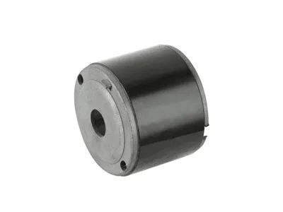
A starter motor pushes several hundred amperes through its brushes and field for a few seconds at a time. Those currents bring requirements a wiper or window casing never meets: bushing and terminal insulation that holds up under electrical stress, brush-holder interfaces that resist heat and vibration, and grounding paths that carry cranking current without heating at the joints. The auto starter motor casing is where these electrical duties meet its mechanical ones, and getting them right is largely about the formed features that mount, insulate and ground the starter’s electrical parts.
Terminals and insulation: kept apart on purpose
The starter’s main terminals and any solenoid connections must be electrically isolated from the casing, and stay isolated through heat, vibration and contamination. In a drawn steel casing, that isolation comes from insulated bushings and formed seating features – a counterbore or stepped hole whose depth and diameter set the insulation’s compression, rather than a simple punched hole that lets the insulator rattle. Our casings hold those seating features by coining or sizing so the insulator sits at a consistent compression, and we specify the insulator’s supplier interface in the drawing because a terminal that loosens its seal is a cranking failure and a fire risk. This is the same “design the pair, not the hole” logic used on sealing grommets, applied where the stakes are higher.
Brush holder interface
The brush holder lives inside the casing, subject to brush spring loads, armature vibration and the heat of current transfer. Its mounting features in a drawn casing – formed lands, holes or steps that position the holder relative to the armature’s commutator – must hold alignment so the brushes sit square on the commutator. Misalignment shows up as uneven brush wear and, eventually, as a commutator that arcs. Our casing designs place the brush-holder features by in-strip forming, tied to the same datum that locates the armature bores, so the holder’s alignment inherits the tooling’s accuracy rather than the assembler’s. Where a programme’s casing is supplied with the holder installed, we verify alignment with a gauge that mimics the armature.
Grounding: the casing’s own electrical duty
The starter’s ground path runs through its mounting to the engine block, so the casing’s contact faces and its bolt interfaces carry cranking current. Interrupted or resistive ground paths cause slow cranking and terminal heating, and they commonly trace to coating on the mating faces or to a joint that loosens. Our casings keep the ground-path faces to a defined bare-metal or conductive-coating specification (masked during plating where necessary) and hold the mounting flange’s contact surfaces flat, so the clamping load is uniform. It is a small detail that customers notice only when it is wrong – as a starter that cranks hesitantly and a bolt that runs warm.
Heat and the casing’s dual role
Under-hood soak plus cranking current make the starter casing a warm part, and the casing is also the starter’s main heatsink to the engine. This means the casing’s wall, its flange contact and its finish all matter thermally. We favour finishes that conduct well at the mounting faces (bare or thinly coated), keep the flange’s contact area generous relative to the bolt pattern, and consider wall thickness where the field heat must reach the flange. On programmes where thermal margin is tight, a slightly thicker casing wall near the mounting flange has bought customers measurable thermal headroom at trivial material cost.
A resistive ground path is the usual answer
The casing drawing with terminal and insulator interfaces, brush-holder mounting features, ground-path specification (which faces must be conductive), the under-hood corrosion and thermal specs, and volume. First articles in four to five weeks after die approval, with terminal-seating metrology and ground-path checks included for programmes that specify them.
Traceability on a safety-adjacent part
A starter failure strands a vehicle, and a terminal that arcs is worse than an inconvenience – so starter casing lots carry a heavier documentation burden than accessory parts. Our file per lot includes the coil certificates, the wall map, the terminal-seating measurements and the ground-path verification, keyed to a stamped code on a non-functional face. When a customer opens a field investigation, the lot resolves to its manufacturing history within a day. It is the same traceability architecture we run across the motor family, applied where the consequences of losing it are greatest.
Starters crank slowly when hot
Our starters crank slowly when hot – electrical or mechanical?
Often a resistive ground path through a coated or loosened mounting face. We can measure the interface’s resistance on returned parts and compare against a clean datum – the answer is usually visible in minutes.
Can you mask the ground faces during plating?
Yes, as a standard option; the mask tooling is part of the plating fixture and the conductive areas are dimensioned on the drawing so both sides agree what “bare” means.
Do you install brush holders?
On qualifying volumes, yes – installed and alignment-gauged to your armature print. The holder and its electrical specification stay yours; the mounting and verification become ours.
Automotive Motor Components is the parent range for parts like this one; the overview page gathers the tooling logic, finishing options and tolerance notes that apply across the family.
Specifications
| Item | Auto starter motor casing |
|---|---|
| Brand | AUNOV |
| Designing | Made to your 2D/3D drawings (PDF, DWG, STEP, IGS) – unusual walls, threads or tolerances are feasibility-checked first; changes are priced before they are made. |
| Tooling | Die design and toolmaking stay in house, so a die can be re-cut against the approved drawing, and maintenance is tracked against the part number. |
| Samples | Samples are issued for approval before the run, so the sample is retained as the master, and later batches are gauged back to the signed sample. |
| Materials | Stock covers carbon steel, 304 / 316 stainless steel, aluminium and brass; the final grade is fixed with the drawing review. |
| Surface finish | Phosphating gives coating adhesion; powder coating, e-coating or zinc plating follow, with chrome and nickel on visible faces. |
| Processing | Blanking, multi-stage deep drawing with interstage annealing, trimming and piercing, coining, then finishing. |
| Equipment | Mechanical presses 5-250 T, hydraulic presses 250-500 T, an in-line annealing furnace, and CNC turning for secondary work. |
| Tolerance | +/-0.05 mm to +/-0.1 mm across the part; tighter bands confirmed against the die before the quotation is fixed. |
| Delivery terms | CIF or DDP, with FOB available, payment by T/T, L/C at sight or D/P; repeat orders reuse the approved first article. |
Related Products


Request a Quote for This Part
Send a drawing or sketch — get material advice, tooling cost and a per-piece price within 24 hours (working days).