
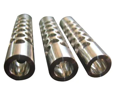
A precision turned and milled component is a category rather than a part, and the honest thing to say about it is that it has no intrinsic engineering content. What it has is a process, and the process has a specific discipline that determines whether the result is precise: on a part that is both turned and milled, the setups are where the precision is won or lost, and the number of setups is decided by the drawing rather than by the machine.
That is the thread through this page. Everything else – the tolerance allocation, the material choices, the inspection plan – follows from whether the part can be made in one setup or three.
Setups, which is the real subject
A setup is a clamping. Every setup introduces a positional error, and the errors accumulate. So the drawing’s job is to make the part’s features groupable into as few clamps as possible, and three geometric decisions do almost all of that work.
- Put the features that must be related to each other on one face. This is the single most valuable thing a designer can do for a precision part, and it costs nothing. A part whose holes are all on one face can be machined in one setup with all of them referenced to one datum, and their relationship is set by the machine. The same holes on three faces need three setups and their relationship is set by three fixturings.
- Make the turned features concentric to the milled features by construction. If the bore and the outside diameters are turned in one clamping and the face features are milled in the same clamping, then the bore, the OD and the face holes are all concentric by virtue of the machine’s axes. If the bore is finished after the milling, that relationship is now a tolerance instead of a consequence.
- Leave a clamping land, and make it somewhere that does not matter. A part with no flat reference and no cylindrical reference cannot be fixtured repeatably, and the shop will use something incidental. A designed clamping land – a small flat, a short cylinder, a spotface – turns the fixturing from a problem into a decision.
And the consequence for tolerance: the relationships between features machined in one setup are inherently better than the relationships between features machined in separate setups. So a tolerance scheme that ignores this is asking for tolerances to be paid for that geometry could have given away for free. The reverse is also true: a dimension that is a feature’s position relative to a different face is a setup-dependent dimension and it is worth the money only when it is functionally necessary.
What a turn-mill does, and when it is the right machine
A turn-mill is a lathe with a live milling spindle, and it changes what a small precision part can be. Four specific capabilities and four specific limits.
- Off-centre milling in the same clamping as the turning. This is the main one. A part with an eccentric feature – a hole off the axis, a slot, a flat, a cross-hole – can be milled without a second setup, and the eccentric feature is then positioned by the machine rather than by a fixture.
- A wide envelope. The part stays in one clamping, so a feature at a distance from the axis is reachable that would be difficult on a machining centre.
- Genuine rigidity for short features. Turning has very good rigidity close to the spindle, and for a short feature or a small face that is better than a machining centre.
- The limit: deep cavities and large faces. A milling spindle can reach less deep and cut less wide than a machining centre’s. A part with a deep pocket or a broad flat surface is a machining-centre part even if it is also turned.
So the process decision on a turned-and-milled part is: if all the milling is shallow, short and near the axis – cross-holes, flats, slots, small eccentric features – a turn-mill is ideal and it removes setups. If the milling involves a deep cavity or a large face, the part will end up moving to a machining centre for that operation, and the setups have to be planned around it.
Austenitic stainless steel changes the precision you can hold
Standard stock: carbon steel, 304 and 316 stainless steel, aluminium and brass, with mill certificates and heat numbers on the first article. Four specific points on precision work.
- Stainless Steel changes the precision achievable, not just the speed. Austenitic stainless steel work-hardens, galls and produces a cut surface that is not as stable as a mild steel’s. On a part where the tolerance is tight and the material is stainless steel, the process discipline – rigid workholding, no interruption on a finished feature, positive rake, sharp tools, consistent coolant – is what determines whether the tolerance is repeatable. This is the same point that appears on every stainless steel page on this site and it bears repeating because it is the mechanism rather than the rule.
- Aluminium’s problem on a precision part is burrs and thermal growth. Aluminium cuts fast and produces a burr that will not break off, and it moves with temperature – so a part measured at a different temperature from the machine will be a different size. On a tight-tolerance aluminium part, a defined measurement temperature is not a nicety.
- Brass is the easiest to machine to a fine tolerance and the easiest to deform. On a small precision brass part the risk is not the machining but the handling and the assembly, because brass will deform under a clamp and stay deformed.
- Carbon steel is the reference case, and on a part where the tolerance is genuinely tight it is often the most sensible material, because it machines predictably and holds its size. It corrodes, and a corrosion-resistant requirement may override the precision argument.
Where a tight band meets a plating, the dimension has to allow for it
Zinc, nickel or chrome plating, anodising, passivation or e-coat, with the finish inspected alongside the dimensional report. Three items that are specific to precision turned and milled work.
- Where a tolerance is tight and a plating will be applied, the dimensions must be specified post-plating with an allowance, or the critical surfaces masked. A plating that changes a fit by twice its thickness on a dimension held to a few microns is a design problem, not a finishing problem.
- On a precision part, the finish’s effect on a sliding or a gauging surface matters. A plated gauge surface is a different surface, and on a part that will be measured or will slide, the finish needs to be specified as a functional characteristic.
- Anodising and precision aluminium – the same rule: every anodised dimension grows, every anodised bore closes, and on a part whose whole purpose is precision this either has to be designed around or masked.
Features that must relate to each other are held as position and orientation
+/-0.01 mm on turned and milled features, GD&T from the print, PPAP-style reports on request. On a precision turned and milled part the flagged dimensions should be chosen by asking what each one is for.
- Features that must be related to each other, held as position and orientation tolerances to a named datum, rather than as separate coordinate dimensions. This is the honest way to write a relationship and it is the way a CMM reports it.
- Concentricity of the turned features to the datum axis, which is the tolerance that the one-setup discipline is buying, and therefore the one that should be tightest.
- Flatness of the face that everything registers against, and its perpendicularity to the axis.
- Any feature that will carry a fastener at a specified torque, – a bearing surface’s flatness and its local material thickness.
- Surface finish on any functional face as its own requirement.
- General dimensions and any feature that is only there for looks at a general band, post-finish.
A conformance report is only credible with heat numbers attached
- CMM inspection of the flagged dimensions, reported as actual values and as the relationships rather than as separate sizes.
- A conformance report on the first article, with the dimensional data, the material certification, the heat numbers, and the finish condition all recorded – which is what PPAP-style reporting is for and on a precision part it is the difference between a controlled component and a purchased one.
- In-process checks between stages rather than only at the end. On a multi-operation part this is what catches a turning operation that has started to drift before it has produced a batch of parts that are all inside tolerance and all outside the requirement.
- Functional fit checks where a representative mating part exists, because on a precision part the assembly check tests the tolerance stack and no single measurement does.
- Surface finish measured on the functional faces and reported separately from the general finish.
- Where the tolerance is genuinely beyond normal capability, that should have been established from capability data before the quotation rather than discovered on the first article.
Which features must relate, and by how much
Which features on this part actually have to be related to each other, and by how much? That is the question that decides both the process and the price, and it is very rarely asked. On a typical precision turned and milled part, of the twenty dimensions on the drawing, perhaps three are functionally critical and the other seventeen are carrying general tolerances and will be produced to whatever the machine holds. If the three critical features can all be machined in one clamping – which usually means putting them on one face and turning their reference features in the same setup – then the part is a single-operation job and it will be both cheaper and better. If they cannot be related in one clamping, then the tolerance stack between them has to be built on the drawing, deliberately, and the drawing should say how it is achieved. So the useful question at enquiry is: name the two or three dimensions that matter, and say how accurately they must relate. Two minutes of that conversation routinely removes a setup from the process, and a setup removed from the process is worth more than any tolerance that can be bought.
CNC Machining Parts is the parent range for parts like this one; the overview page gathers the tooling logic, finishing options and tolerance notes that apply across the family.
Specifications
| Item | Precision CNC Turning and Milling Components |
|---|---|
| Brand | AUNOV |
| Designing | Driven by your drawing or a physical sample – unusual walls, threads or tolerances are feasibility-checked first; the agreed version governs every later batch. |
| Tooling | Our toolroom covers die design, wire-cut EDM and maintenance, so a die can be re-cut against the approved drawing, and the die remains dedicated to your part. |
| Samples | Pre-production samples come with a full inspection report, so the part is proven before it is made in volume, and later batches are gauged back to the signed sample. |
| Materials | Standard stock: carbon steel (SPCC / DC01), 304 / 316 stainless steel, aluminium, brass; mill certificates and heat numbers accompany the first article. |
| Surface finish | Zinc, nickel or chrome plating, anodising, passivation or e-coat; the finish is inspected with the dimensional report on the first article. |
| Processing | Turning, milling and drilling sequenced to minimise handling and re-chucking; in-process checks sit between stages, not only at the end. |
| Equipment | 12 CNC turning centres with automatic bar feeders, with in-house toolmaking to keep dies and fixtures maintained. |
| Tolerance | +/-0.01 mm on turned and milled features; GD&T per drawing, PPAP-style reports on request. |
| Delivery terms | FOB, CIF or DDP per Incoterms 2020, T/T or L/C, with D/P accepted on repeat business; repeat orders reuse the approved first article. |
Related Products


Request a Quote for This Part
Send a drawing or sketch — get material advice, tooling cost and a per-piece price within 24 hours (working days).